


6A-5
POWER TRIM
90-13645--2
495
Troubleshooting
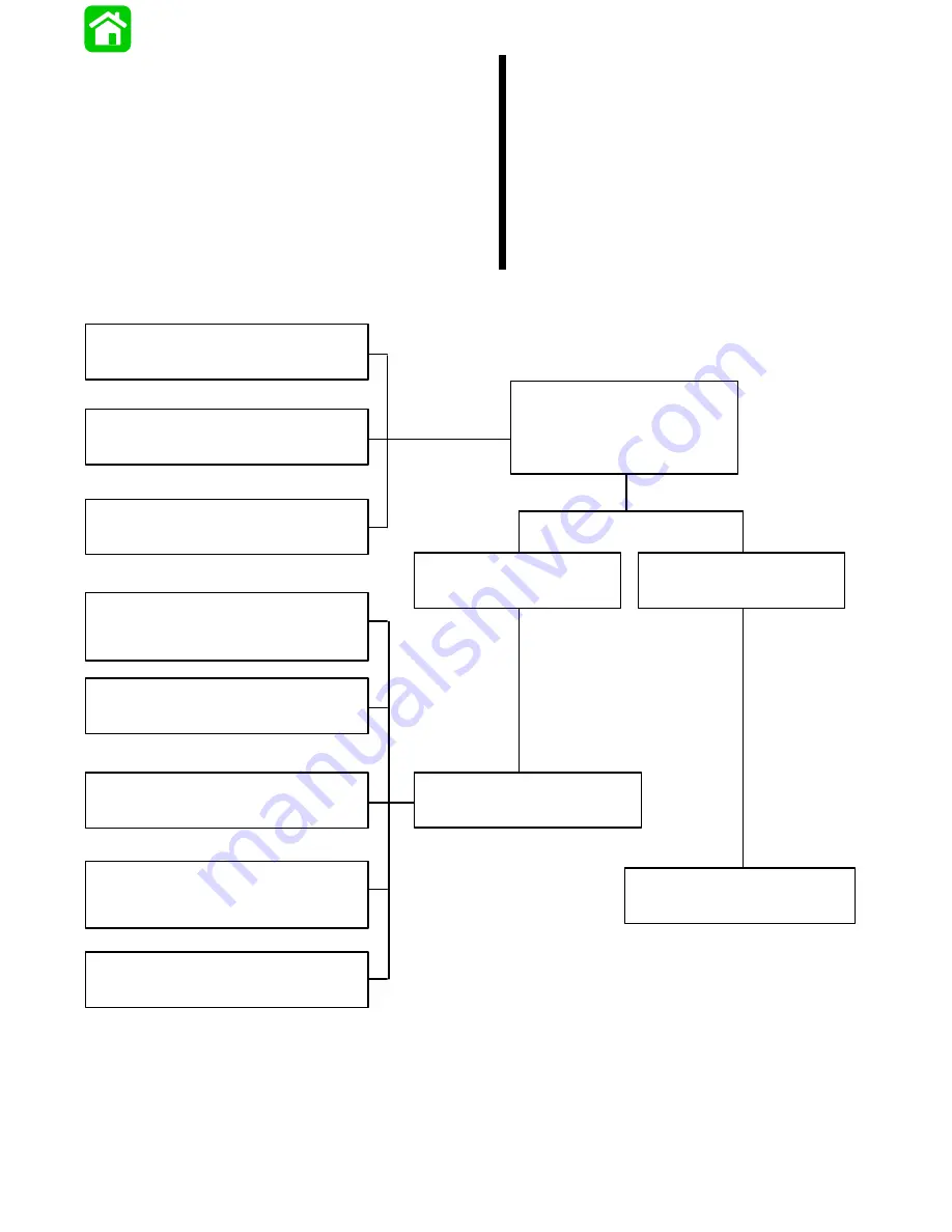
Determining if Problem is Electrical or
Hydraulic
When a problem is encountered with the Power Trim
system, the first step is to determine whether the mal-
function is in the “electrical system” or the “hydraulic
system.” Refer to the following chart to determine
which system is at fault.
Engine will not hold a trimmed
position or will not remain tilted for
any extended period.
Engine will not return completely to
“down” position or returns part way
with jerky motion.
Engine will not trim up or down.
Engine trims up, will not trim down.
Engine trims down, will not trim up.
Engine thumps when shifted.
Engine trails out when backing off
throttle at high speed.
Engine will not hold trim position
when in reverse.
Determine if Power Trim
pump motor operates when
appropriate trim circuit is
activated.
Pump motor operates.
Pump motor does not
operate.
Refer to “Hydraulic System
Troubleshooting.”
Refer to “Electrical System
Troubleshooting.”
Trouble Chart
Summary of Contents for 100
Page 4: ...GENERAL INFORMATION AND SPECIFICATIONS 1 ...
Page 18: ...IGNITION SYSTEM ELECTRICAL AND IGNITION A 2 ...
Page 30: ...11669 BATTERY CHARGING SYSTEM AND STARTING SYSTEM ELECTRICAL AND IGNITION B 2 ...
Page 58: ...22480 TIMING SYNCHRONIZING ADJUSTING ELECTRICAL AND IGNITION C 2 ...
Page 71: ...WIRING DIAGRAMS ELECTRICAL AND IGNITION D 2 ...
Page 86: ...FUEL SYSTEM AND CARBURETION A 3 ...
Page 118: ...OIL INJECTION SYSTEM B 3 ...
Page 127: ...20032 3 CYLINDER ENGINES POWERHEAD A 4 ...
Page 168: ...791 H GEAR HOUSING LOWER UNIT A 5 ...
Page 170: ...5A 1 90 13645 2 1095 LOWER UNIT Notes ...
Page 205: ...MID SECTION LOWER UNIT B 5 ...
Page 207: ...5B 1 90 13645 2 495 LOWER UNIT Notes ...
Page 218: ...SHOCK ABSORBER LOWER UNIT C 5 ...
Page 223: ...17250 DESIGN I SIDE FILL RESERVOIR POWER TRIM A 6 ...
Page 233: ...6A 9 POWER TRIM 90 13645 2 495 Commander Side Mount Remote Control Wiring Diagram ...
Page 268: ...DESIGN II AFT FILL RESERVOIR POWER TRIM B 6 51344 ...
Page 305: ...SINGLE RAM POWER TRIM C 6 51485 ...
Page 309: ...6C 3 90 13645 2 495 POWER TRIM Notes ...
Page 340: ...50099 ENGINE ATTACHMENTS ENGINE INSTALLATION 7 A ...
Page 369: ...TILLER HANDLE AND CO PILOT OUTBOARD MOTOR INSTALLATION ATTACHMENTS 7 B ...
Page 371: ...7B 1 90 13645 2 495 OUTBOARD MOTOR INSTALLATION ATTACHMENTS Notes ...