


7A-15
ENGINE ATTACHMENTS
90-13645--2
495
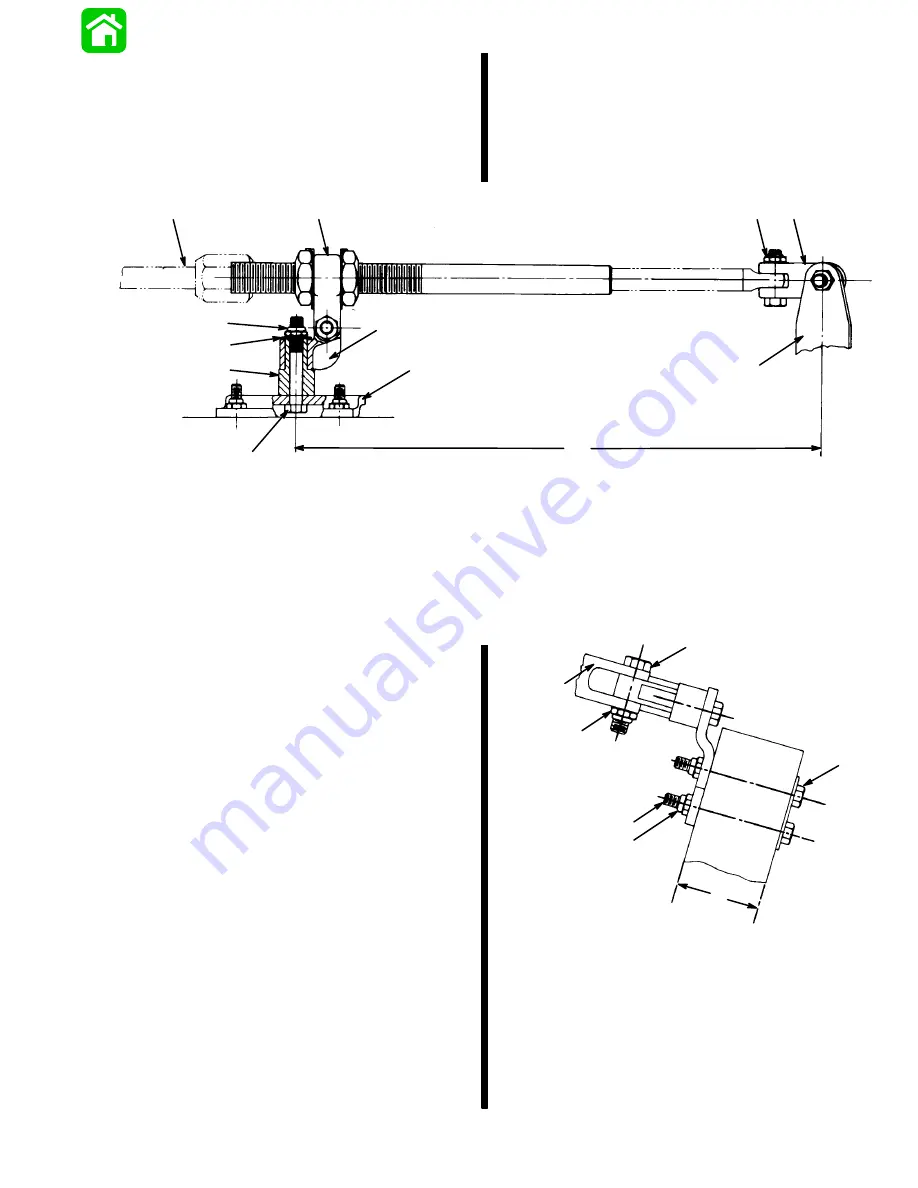
1. Lubricate both holes in pivot block (Figure 1) with
Quicksilver 2-4-C w/Teflon.
2. Place pivot block on pivot spacer and secure to
transom bracket with 3/8 in. x 2-1/2 in. (9.5mm x
63.5mm) bolt, flat washer and locknut, as shown
in Figure 1. Torque locknut to 20 lbs. ft. (27.1 N
m).
a
b
c
d
e
f
g
h
i
j
k
l
a - Ride-Guide Cable
b - Ride-Guide Yoke
c - Pivot Block
d - Pivot Spacer
e - 15 in. (38.1cm) (Centerline of Attaching Kit Pivot to Centerline
of Outboard)
f - Pivot Attaching Locknut - Torque to 20 lbs. ft. (27.1 N
m)
g - Outboard Steering Arm
h - “Clevis Kit”
i - Ride-Guide Cable Attaching Locknut - Torque to 10 lbs. ft.
(13.5 N
m)
j - Bolt - 3/8 in. x 2-1/2 in. (9.5mm x 63.5mm)
k - Flat Washer
l - Transom Bracket
Figure 1
3. Place Ride-Guide yoke on pivot block and secure
with 7/16 in. x 1-3/4 in. (11.1mm x 44.5mm) bolt
and locknut, as shown in Figures 1 and 2. Torque
locknut to 10 lbs. ft. (13.5 N
m), then back off
1/4-turn.
4. Install one cable tube jam nut onto steering cable
tube. Place tab washer over Ride-Guide yoke,
then insert cable tube thru tab washer and yoke.
Install second cable tube jam nut onto cable tube
but do not tighten at this time (Figure 3).
5. Position transom attaching kit on transom as
follows:
a. Determine centerline of outboard, then mea-
sure 15 in. (38.1cm) over from this centerline
and draw a vertical line on transom (Figure 1).
b. Position attaching kit on transom so that
transom bracket is centered on the 15 in.
(38.1cm) (Figure 1) at a height where the
center of Ride-Guide yoke is even with, or
not more than 1/2 in. (12.7mm) above top
edge of transom (Figure 3).
a
b
c
d
e
f
g
a - Transom Backing Plate
b - Bolt - 5/16 in. x 3-1/4 in. (7.9mm x 82.5mm)
c - Locknut - Torque to 10 lbs. ft. (13.5 N
m)
d - Ride-Guide Yoke Attaching Locknut - Torque to 10 lbs. ft.
(13.5 N
m) Then Back Off 1/4-Turn.
e - 2-3/8 in. (60.3mm) Maximum Transom Thickness
f - Bolt - 7/16 in. x 1-3/4 in. (11.1mm x 44.5mm)
g - Ride-Guide Yoke
Figure 2
Summary of Contents for 100
Page 4: ...GENERAL INFORMATION AND SPECIFICATIONS 1 ...
Page 18: ...IGNITION SYSTEM ELECTRICAL AND IGNITION A 2 ...
Page 30: ...11669 BATTERY CHARGING SYSTEM AND STARTING SYSTEM ELECTRICAL AND IGNITION B 2 ...
Page 58: ...22480 TIMING SYNCHRONIZING ADJUSTING ELECTRICAL AND IGNITION C 2 ...
Page 71: ...WIRING DIAGRAMS ELECTRICAL AND IGNITION D 2 ...
Page 86: ...FUEL SYSTEM AND CARBURETION A 3 ...
Page 118: ...OIL INJECTION SYSTEM B 3 ...
Page 127: ...20032 3 CYLINDER ENGINES POWERHEAD A 4 ...
Page 168: ...791 H GEAR HOUSING LOWER UNIT A 5 ...
Page 170: ...5A 1 90 13645 2 1095 LOWER UNIT Notes ...
Page 205: ...MID SECTION LOWER UNIT B 5 ...
Page 207: ...5B 1 90 13645 2 495 LOWER UNIT Notes ...
Page 218: ...SHOCK ABSORBER LOWER UNIT C 5 ...
Page 223: ...17250 DESIGN I SIDE FILL RESERVOIR POWER TRIM A 6 ...
Page 233: ...6A 9 POWER TRIM 90 13645 2 495 Commander Side Mount Remote Control Wiring Diagram ...
Page 268: ...DESIGN II AFT FILL RESERVOIR POWER TRIM B 6 51344 ...
Page 305: ...SINGLE RAM POWER TRIM C 6 51485 ...
Page 309: ...6C 3 90 13645 2 495 POWER TRIM Notes ...
Page 340: ...50099 ENGINE ATTACHMENTS ENGINE INSTALLATION 7 A ...
Page 369: ...TILLER HANDLE AND CO PILOT OUTBOARD MOTOR INSTALLATION ATTACHMENTS 7 B ...
Page 371: ...7B 1 90 13645 2 495 OUTBOARD MOTOR INSTALLATION ATTACHMENTS Notes ...