


6A-35
POWER TRIM
90-13645--2
495
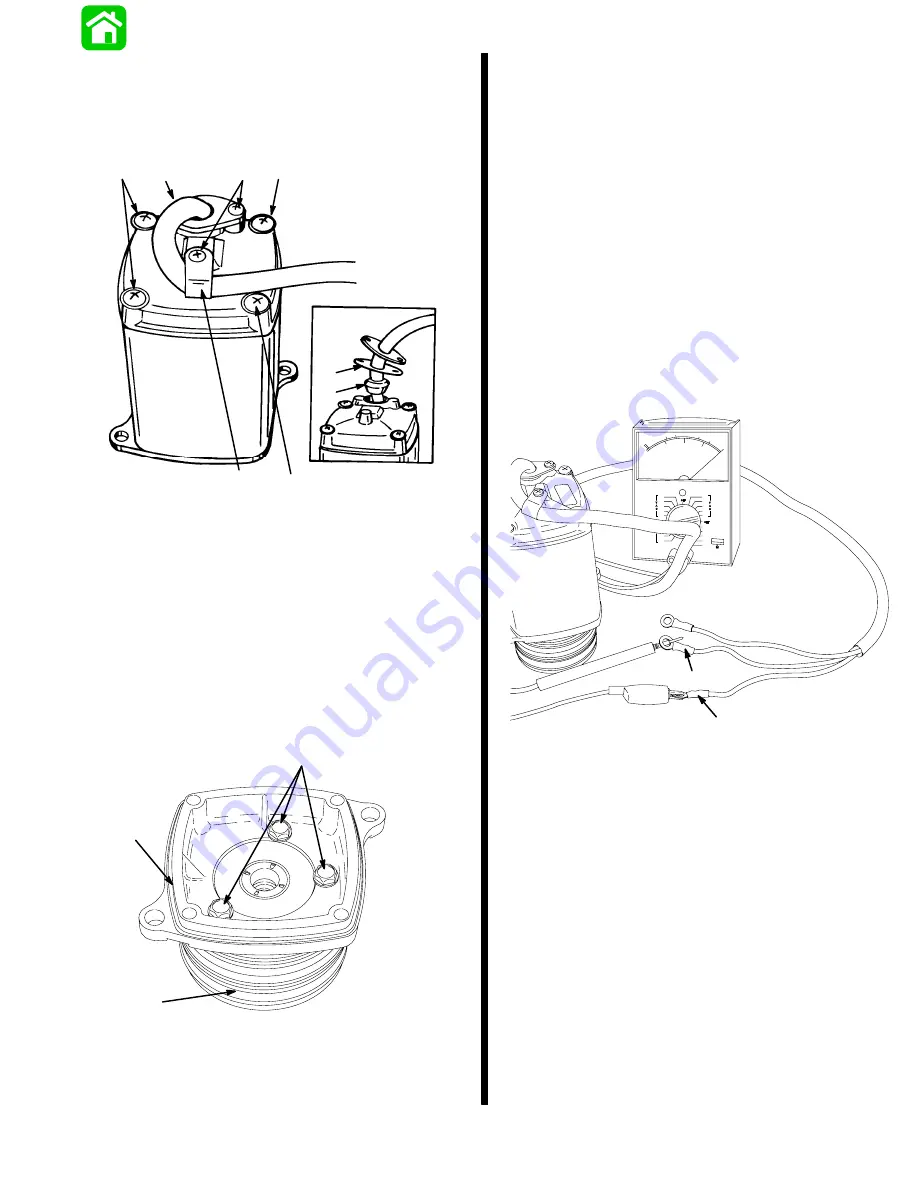
2. Remove screws and clamp.
Remove screws.
Lift motor from end cap, taking care not to drop
armature.
51345
a
b
c
d
e
a
c
c
a - Screw (3)
b - Clamp
c - Screw (4)
d - Gasket
e - Grommet
3. Remove bolts.
NOTE: Some motors use 2 bolts to secure end frame
cap.
Lift end cap from pump.
Follow “Reassembly” and “Installation” instruc-
tions in “Motor Repair,” following.
18469
a
b
c
a - Bolts
b - End Cap
c - Pump
Motor and Electrical
Tests/Repair
Thermal Overload Switch Test
IMPORTANT: If trim pump has just been operated,
do not run pump for approximately one minute be-
fore testing thermal overload switch. After this
period of time the switch should close (reset it-
self) and pump again may be operated. Perform
the following check(s) only if switch does not re-
set itself.
MOTOR ASSEMBLED
Connect Ohmmeter (R x 1 scale) leads as shown. If
switch is good, full continuity (zero ohms) will be indi-
cated. If full continuity is not indicated, disassemble
motor and recheck switch per instructions, following.
18459
a
b
a - Motor Wire (BLUE)
b - Motor Wire (BLACK)
Summary of Contents for 100
Page 4: ...GENERAL INFORMATION AND SPECIFICATIONS 1 ...
Page 18: ...IGNITION SYSTEM ELECTRICAL AND IGNITION A 2 ...
Page 30: ...11669 BATTERY CHARGING SYSTEM AND STARTING SYSTEM ELECTRICAL AND IGNITION B 2 ...
Page 58: ...22480 TIMING SYNCHRONIZING ADJUSTING ELECTRICAL AND IGNITION C 2 ...
Page 71: ...WIRING DIAGRAMS ELECTRICAL AND IGNITION D 2 ...
Page 86: ...FUEL SYSTEM AND CARBURETION A 3 ...
Page 118: ...OIL INJECTION SYSTEM B 3 ...
Page 127: ...20032 3 CYLINDER ENGINES POWERHEAD A 4 ...
Page 168: ...791 H GEAR HOUSING LOWER UNIT A 5 ...
Page 170: ...5A 1 90 13645 2 1095 LOWER UNIT Notes ...
Page 205: ...MID SECTION LOWER UNIT B 5 ...
Page 207: ...5B 1 90 13645 2 495 LOWER UNIT Notes ...
Page 218: ...SHOCK ABSORBER LOWER UNIT C 5 ...
Page 223: ...17250 DESIGN I SIDE FILL RESERVOIR POWER TRIM A 6 ...
Page 233: ...6A 9 POWER TRIM 90 13645 2 495 Commander Side Mount Remote Control Wiring Diagram ...
Page 268: ...DESIGN II AFT FILL RESERVOIR POWER TRIM B 6 51344 ...
Page 305: ...SINGLE RAM POWER TRIM C 6 51485 ...
Page 309: ...6C 3 90 13645 2 495 POWER TRIM Notes ...
Page 340: ...50099 ENGINE ATTACHMENTS ENGINE INSTALLATION 7 A ...
Page 369: ...TILLER HANDLE AND CO PILOT OUTBOARD MOTOR INSTALLATION ATTACHMENTS 7 B ...
Page 371: ...7B 1 90 13645 2 495 OUTBOARD MOTOR INSTALLATION ATTACHMENTS Notes ...