


4A-15
90-13645--2
495
POWERHEAD
IMPORTANT: On some engines, BOTH the piston
rod and rod cap bolt holes are threaded. The rod
cap and rod must be aligned and held tight togeth-
er when threading in rod cap bolts. Check mating
surfaces to be sure that they are tight together af-
ter bolt enters the threads in the piston rod.
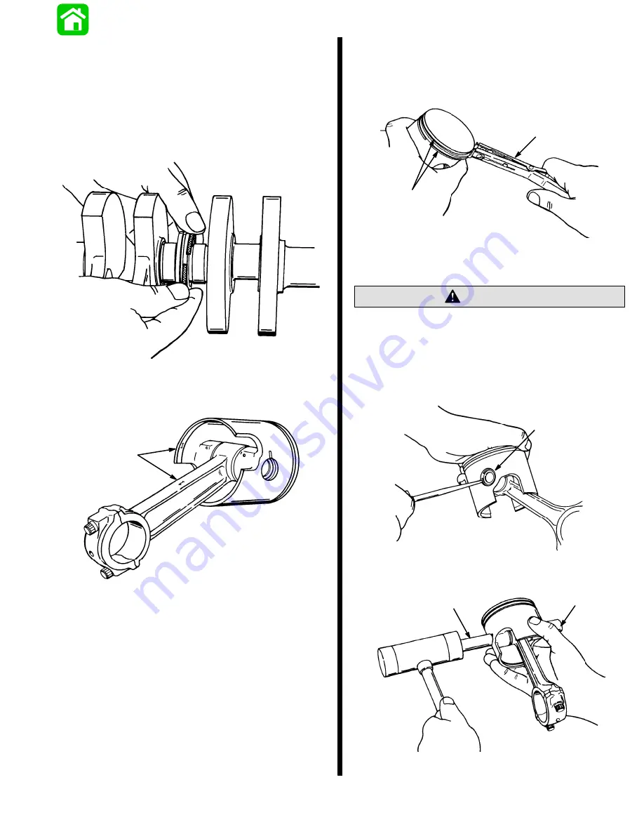
16. Remove main bearing sealing rings - 2 per center
main journal.
51083
17. Using an awl, scribe identification number of con-
necting rod on inside of piston. Reassemble pis-
ton on same connecting rod.
17770
a
a - Scribe Mark
18. Use piston ring expander (91-24697) to remove
piston rings. Always install new piston rings.
NOTE: Cylinders must be honed in order for new rings
to seat properly.
51081
a
b
a - Piston Ring Expander (P/N 91-24697)
b - Piston Rings
Eye protection MUST BE worn while removing
piston pin lockrings from piston.
CAUTION
19. Using an awl, remove piston pin lockrings (a) from
both ends of piston pin. Never re-use piston pin
lockpins. Hold shop cloth over lockring area when
snapping out lockrings.
51083
a
20. Support piston and tap out piston pin (a), using
service tool (b) 91-74607A2, as shown.
51086
a
b
a - Piston Pin
b - Wrist Pin Tool (91-74607A2)
Summary of Contents for 100
Page 4: ...GENERAL INFORMATION AND SPECIFICATIONS 1 ...
Page 18: ...IGNITION SYSTEM ELECTRICAL AND IGNITION A 2 ...
Page 30: ...11669 BATTERY CHARGING SYSTEM AND STARTING SYSTEM ELECTRICAL AND IGNITION B 2 ...
Page 58: ...22480 TIMING SYNCHRONIZING ADJUSTING ELECTRICAL AND IGNITION C 2 ...
Page 71: ...WIRING DIAGRAMS ELECTRICAL AND IGNITION D 2 ...
Page 86: ...FUEL SYSTEM AND CARBURETION A 3 ...
Page 118: ...OIL INJECTION SYSTEM B 3 ...
Page 127: ...20032 3 CYLINDER ENGINES POWERHEAD A 4 ...
Page 168: ...791 H GEAR HOUSING LOWER UNIT A 5 ...
Page 170: ...5A 1 90 13645 2 1095 LOWER UNIT Notes ...
Page 205: ...MID SECTION LOWER UNIT B 5 ...
Page 207: ...5B 1 90 13645 2 495 LOWER UNIT Notes ...
Page 218: ...SHOCK ABSORBER LOWER UNIT C 5 ...
Page 223: ...17250 DESIGN I SIDE FILL RESERVOIR POWER TRIM A 6 ...
Page 233: ...6A 9 POWER TRIM 90 13645 2 495 Commander Side Mount Remote Control Wiring Diagram ...
Page 268: ...DESIGN II AFT FILL RESERVOIR POWER TRIM B 6 51344 ...
Page 305: ...SINGLE RAM POWER TRIM C 6 51485 ...
Page 309: ...6C 3 90 13645 2 495 POWER TRIM Notes ...
Page 340: ...50099 ENGINE ATTACHMENTS ENGINE INSTALLATION 7 A ...
Page 369: ...TILLER HANDLE AND CO PILOT OUTBOARD MOTOR INSTALLATION ATTACHMENTS 7 B ...
Page 371: ...7B 1 90 13645 2 495 OUTBOARD MOTOR INSTALLATION ATTACHMENTS Notes ...