


90-13645--2
1095
3B-2
OIL INJECTION SYSTEM
Filling Oil Tank
1. Quicksilver 2-Cycle Outboard Oil is recom-
mended for this oil injection system. In an emer-
gency, when Quicksilver 2-Cycle Outboard Oil is
not available, substitute a high quality 2-cycle oil
that is intended for outboard use and meets BIA
rating TC-WII or TC-W3, shown on oil container.
BIA rating TC-W is the Boating Industry Associa-
tion’s designation for approved, 2-cycle water-
cooled outboard oils.
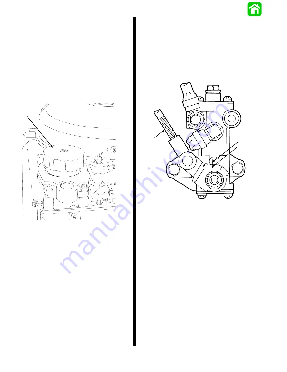
2. Remove fill cap from the oil tank and fill tank with
oil. Retighten the fill cap.
25955
a
a - Fill Cap
Carburetor/Oil Pump
Synchronization
1. While holding throttle arm at idle position, adjust
length of link rod so that stamped mark of oil pump
body aligns with stamped mark of oil pump lever,
and lever is in closed position.
2. Check full travel of link rod that it does not interfere
with hoses, sta-straps, etc.
a
b
c
a - Mark on Body
b - Mark, Fully Closed on Lever
c - Link Rod
Summary of Contents for 100
Page 4: ...GENERAL INFORMATION AND SPECIFICATIONS 1 ...
Page 18: ...IGNITION SYSTEM ELECTRICAL AND IGNITION A 2 ...
Page 30: ...11669 BATTERY CHARGING SYSTEM AND STARTING SYSTEM ELECTRICAL AND IGNITION B 2 ...
Page 58: ...22480 TIMING SYNCHRONIZING ADJUSTING ELECTRICAL AND IGNITION C 2 ...
Page 71: ...WIRING DIAGRAMS ELECTRICAL AND IGNITION D 2 ...
Page 86: ...FUEL SYSTEM AND CARBURETION A 3 ...
Page 118: ...OIL INJECTION SYSTEM B 3 ...
Page 127: ...20032 3 CYLINDER ENGINES POWERHEAD A 4 ...
Page 168: ...791 H GEAR HOUSING LOWER UNIT A 5 ...
Page 170: ...5A 1 90 13645 2 1095 LOWER UNIT Notes ...
Page 205: ...MID SECTION LOWER UNIT B 5 ...
Page 207: ...5B 1 90 13645 2 495 LOWER UNIT Notes ...
Page 218: ...SHOCK ABSORBER LOWER UNIT C 5 ...
Page 223: ...17250 DESIGN I SIDE FILL RESERVOIR POWER TRIM A 6 ...
Page 233: ...6A 9 POWER TRIM 90 13645 2 495 Commander Side Mount Remote Control Wiring Diagram ...
Page 268: ...DESIGN II AFT FILL RESERVOIR POWER TRIM B 6 51344 ...
Page 305: ...SINGLE RAM POWER TRIM C 6 51485 ...
Page 309: ...6C 3 90 13645 2 495 POWER TRIM Notes ...
Page 340: ...50099 ENGINE ATTACHMENTS ENGINE INSTALLATION 7 A ...
Page 369: ...TILLER HANDLE AND CO PILOT OUTBOARD MOTOR INSTALLATION ATTACHMENTS 7 B ...
Page 371: ...7B 1 90 13645 2 495 OUTBOARD MOTOR INSTALLATION ATTACHMENTS Notes ...