

install - concepts - PixMaster - switcher - CG - clips - controls - team - appendix
FLINT
V1.1
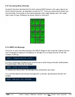
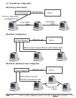
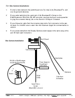
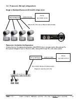
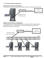
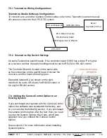
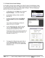
7.3.1 One Camera Installations
1.
Run two video cables to the pan/tilt head: one for video to the Broadcast Pix, and
one for genlock/reference.
2.
Run a serial cable from the serial port of the Broadcast Pix Server to the
B&B Electronics RS-232 to RS-485 converter, as shown below. It is also possible
to plug the converter directly into on the Server’s COM port, if desired.
3.
Run a three wire cable from the converter plug to the 5 pin connector on the pan
tilt head. If a 24 AWG wire is used, then the maximum length for communication is
4000 ft.
4.
Run a power cable from the Display Devices power supply to the same plug at the
pan tilt head used in step two.
Serial Port on
Server
Either COM 1 or Com 2
Power Supply for
Pan-tilt head
and Camera
Serial
Cable
Pan-Tilt head
Video Cables
Video Input
On Switcher
Reference
One Camera Installation
Ground
a
b
RS-232 to RS-485 adaptor
included by Broadcast Pix
7.3.1
5 pin connector


