
install - concepts - PixMaster - switcher - CG - clips - controls - team - appendix
FLINT
V1.1
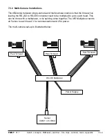
7.3 Installation of Hitachi Cameras
Most of the instructions for how to install this camera control system come from Display
Devices, the makers of the pan/tilt head that is being used by Broadcast Pix. Please refer to
the Display Devices/Eagle manual for more information, there are various dip switches that
must be placed in the correct position depending on the camera model, both in the pan/tilt
head and camera. Ensure that the camera is set to communicate through a PC remote
control at 9600 baud rate and that internal dip switches are set to RS-232C (not RC-Z3). In
addition, each camera must be saved with Travel Limits to ensure proper operation, see
section 7.11.1.
Contents of the Broadcast Pix Hitachi Camera Control Option:
Before you start, check that all of the components are present. They fall in two groups: those
supplied by Broadcast Pix and parts from Display Devices and others that need to be
acquired before installation.
Parts supplied by Broadcast Pix:
- Software Installation CD with option code, comes pre-installed on new systems
- This Operations and Installation Manual
- B&B Electronics 485SD9TB (RS-232 to RS-485 Adapter), two-wire
Parts Needed from Display Devices
- A Pan/Tilt head for each camera, either a PT-50, VT-50, PT-101, VT-101 or similar
- Power supplies for the above heads
- If you are controlling more than one head, you need a splitter, such as a PT-T2
- Power and Control Tee from Display Devices
You also need a camera with a lens for each pan/tilt system that is supported by these
heads, including selected box cameras from Hitachi: HV-D30, HV-D25/27, HV-D15, HV-
D15AS, HV-D5 or D5W, HV-D20A, Z-2500, Z-3500, Z-4000, DK-H31 or SK-31B/ Sony:
DXC-390, DXC-990 or HDC-X300/310. Panasonic: AW-E350, AW-E650,
AW-E750, AW-E655, AW-E860 or AK-HC1500G. JVC: KY-F560U.
For an up to date list, visit www.eaglepantilt.com.
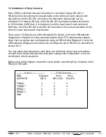
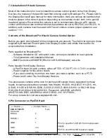
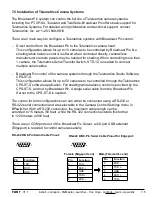
5-Pin Connecter on Pan/Tilt Head:
7.3
------Server------ -----Camera Head------
B&B 485SD9TB
5-pin
Connector
TXD(A) -
2
TXD(B) +
3
GND
1
GND
n/a
+12V
n/a
Pin 4 is used for +24V DC from main power
supply.
Pin 5 is used fro GND to power supply.


