482
32072H–AVR32–10/2012
AT32UC3A3
1.
Wait until RHR is empty, stretching low period of TWCK. SR.RXRDY indicates the state
of RHR. Software or the Peripheral DMA Controller must read any data byte present in
RHR.
2.
Release TWCK generating a clock that the slave uses to transmit a data byte.
3.
Place the received data byte in RHR, set RXRDY.
4.
If NBYTES=0, generate a NAK after the data byte, otherwise generate an ACK.
5.
Decrement NBYTES
6.
If (NBYTES==0) and STOP=1, transmit STOP condition.
Writing CMDR with START=STOP=1 and NBYTES=0 will generate a transmission with no data
bytes, ie START, DADR+R, STOP
The TWI transfers require the master to acknowledge each received data byte. During the
acknowledge clock pulse (9th pulse), the slave releases the data line (HIGH), enabling the mas-
ter to pull it down in order to generate the acknowledge. All data bytes except the last are
acknowledged by the master. Not acknowledging the last byte informs the slave that the transfer
is finished.
RXRDY is used as Receive Ready for the Peripheral DMA Controller receive channel.
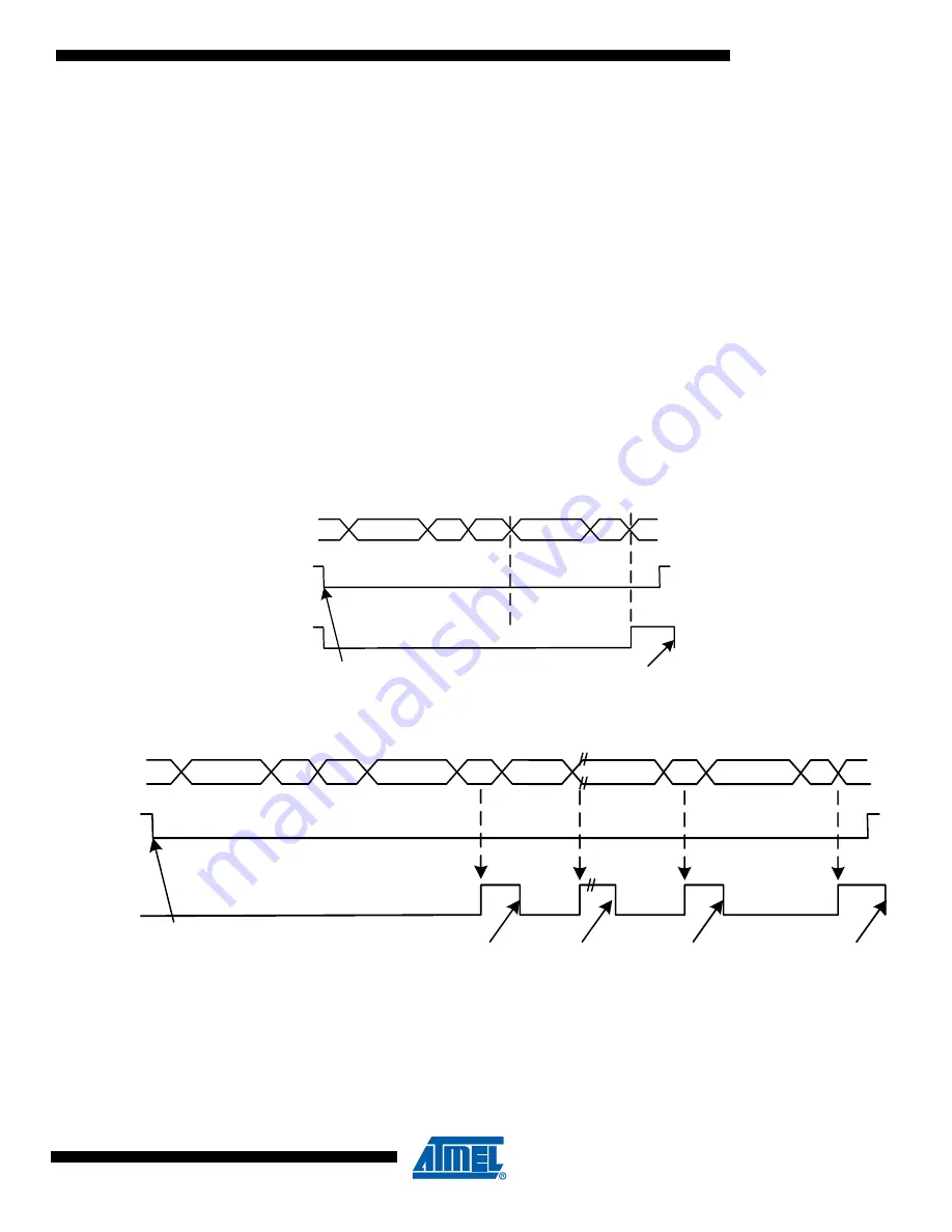
Figure 23-8. Master Read with One Data Byte
Figure 23-9. Master Read with Multiple Data Bytes
TWD
SR.IDLE
RXRDY
Write START &
STOP bit
NBYTES set to 1
Read RHR
S
DADR
R
A
DATA
N
P
TWD
SR.IDLE
RXRDY
Write START +
STOP bit
NBYTES set to m
S
DADR
R
A
DATAn
A
DATAn+m-1
A
N
DATAn+m
P
Read RHR
DATAn
DATAn+1
Read RHR
DATAn+m-2
Read RHR
DATAn+m-1
Read RHR
DATAn+m
Send STOP
When NBYTES=0
Summary of Contents for AT32UC3A3128
Page 61: ...61 32072H AVR32 10 2012 AT32UC3A3 PLLEN PLL Enable 0 PLL is disabled 1 PLL is enabled...
Page 592: ...592 32072H AVR32 10 2012 AT32UC3A3 Manchester Configuration Register on page 614...
Page 989: ...989 32072H AVR32 10 2012 AT32UC3A3 37 2 Package Drawings Figure 37 1 TFBGA 144 package drawing...
Page 991: ...991 32072H AVR32 10 2012 AT32UC3A3 Figure 37 3 VFBGA 100 package drawing...


