SET UP
Page5-10
5-6.1.4 Function Code A3 – SE (Station Expander)
5-6.1.5 Function Code A4 – Neutral Indication Tone
5-6.2 Throttle Functions
5-6.2.1 Throttle Basic Functions
5-6.2.1.1
Function Code E5 – Throttle Pause Following Shift
NOTE: T
HIS
M
ANUAL
DOES
NOT
GO
INTO
DETAIL
ON
THE
S
TATION
E
XPANDER
INSTALLATION
AND
ADJUSTMENTS
. F
OR
FURTHER
INFORMATION
ON
THE
S
TATION
E
XPANDER
,
CONTACT
YOUR
LOCAL
ZF M
ATHERS
R
EPRESENTATIVE
.
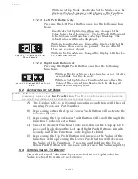
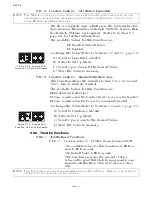
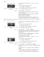
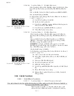
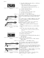
Figure 5-14: Display LED
Function A3 Set Up Activated
The SE is a separate unit, which gives the System the abil-
ity to increase the number of Remote Stations, if more than
five Remote Stations are required. (Refer to Section 8-3,
page 8-4, for further information)
The available Values for this Function are:
00 Disabled (Default Value)
01 Enabled
To change the Value (Refer to Sections
5-2 and 5-3, page 5-5
):
A) Scroll to Function Code
A3
.
B) Activate Set Up Mode.
C) Scroll Up or Down to the desired Value.
D) Store the Value to memory.
This Function allows the installer to turn ON a 1/2 second,
50 Hz. tone to indicate Neutral.
The available Values for this Function are:
00
Disabled (Default Value)
01
Tone sounds when the Control Head’s lever reaches Neutral
02
Tone sounds when the Processor commands Neutral
To change the Value (Refer to Sections
5-2 and 5-3, page 5-5
):
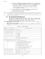
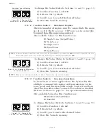
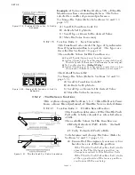
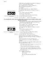
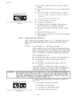
Figure 5-15: Display LED
Function A4 Set Up Activated
A) Scroll to Function Code
A4
.
B) Activate Set Up Mode.
C) Scroll Up or Down to the desired Value.
D) Store the Value to memory.
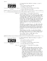
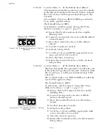
The available Values for this Function are
00.0
sec-
onds to
05.0
seconds.
The Default Value is
00.5
seconds.
This Function programs the amount of delay
between the point that Clutch engagement is com-
manded and throttle is allowed to increase above
Idle.
NOTE: T
HIS
F
UNCTION
IS
TYPICALLY
PROGRAMMED
DURING
D
OCK
T
RIALS
. R
EFER
TO
THE
APPROPRI
-
ATE
S
ECTION
6-8,
PAGE
6-6,
OR
6-9,
PAGE
6-7.
Содержание ClearCommand 9000 Series
Страница 1: ...ClearCommand 9000 Series Installation Operation and Troubleshooting Manual MM9000 I Rev C 2 5 08...
Страница 132: ......
Страница 133: ...APPENDIX A...
Страница 134: ......
Страница 139: ......
Страница 140: ...Page A 4...
Страница 143: ......
Страница 144: ...10...
Страница 148: ...Page A 18...
Страница 149: ...Page A 19 TEMPLATE...
Страница 150: ...Page A 20...
Страница 152: ...Page A 22...
Страница 154: ...Page A 24...
Страница 156: ...Page A 26...
Страница 157: ...Page A 27 Drawing 11488D 1 Twin Screw Single APS Connection Alternate Remote Switch...
Страница 158: ...Page A 28...
Страница 159: ...Page A 29 Drawing 11488D 2 Twin Screw Dual APS Connections...
Страница 160: ...Page A 30...
Страница 161: ...Page A 31 Drawing 11488D 3 APS Notes Page...
Страница 162: ...Page A 32...
Страница 164: ...Page A 34...
Страница 166: ...Page A 36...
Страница 170: ...Page A 40...
Страница 172: ...Page A 42...
Страница 176: ...Page A 46...
Страница 178: ...Page C 48 ZF Mathers LLC 12125 Harbour Reach Drive Suite B Mukilteo WA 98275...
Страница 179: ...APPENDIX B...
Страница 180: ......
Страница 234: ...Appendix B 6...
Страница 238: ...Appendix B 10...
Страница 242: ...Appendix B 14...
Страница 247: ...Service Field Test Unit Reference Manual MM13927 Rev E 4 07...
Страница 248: ......
Страница 250: ...Page ii Table of Contents...
Страница 264: ...SERVICE FIELD TEST UNIT MM13927 RvD 10 03 Page 3 2...
Страница 265: ...APPENDIX C...
Страница 266: ......
Страница 267: ...Appendix C 1 Drawing 12284A 1 ClearCommand Diagram all options...
Страница 268: ...Appendix C 2...
Страница 269: ...Appendix C 3 Drawing 12284A 2 ClearCommand Circuit Board Connections...
Страница 270: ...Appendix C 4...
Страница 271: ...Appendix C 5 Drawing 12284A 3 ClearCommand Drawing Notes Page...
Страница 272: ...Appendix C 6...


