OPERATION
Page 2-9
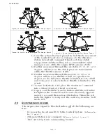
nals are compared with one another over a serial
communication line. If the Synchronization Criteria
(described in Section 2-11.2) is met, the throttle command
signal of the engine running at the higher RPM is lowered,
until the RPM's of both engines match.
2-11.2 Synchronization Criteria
Synchronization Criteria is met when all of the following are
true:
• Both Control Head levers are commanding at least 5% of the
throttle range.
• The commanded throttles are within a 10% window of one
another (approximately 6 degrees).
• Both Control Head levers are commanding Ahead clutch engage-
ment.
2-11.3 Synchronization Indications
The green LED located on the Control Head indicates the status
of synchronization.
• In Active Synchronization the green LED
blinks
every time there
is a change in the commanded throttle.
• When the green LED is lit
steady
, the engines are synchronized.
• When the green LED is
not lit
, the engines are not synchronized
and the Control System is not attempting to do so.
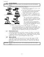
2-11.4 Turning Synchronization OFF:
A)Ensure that the Control Head's levers are positioned to a
point where Synchronization Criteria are met.
B)Press and hold the transfer button until the green LED blinks
and then goes out (approximately 2 seconds).
C)Synchronization is now OFF.
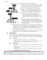
2-11.5 Turning Synchronization ON:
A)Ensure that the Control Head's levers are positioned to a
point where Synchronization Criteria are met.
B)Press and hold the transfer button until the green LED lights
(approximately 2 seconds).
•The green LED will blink as the system is working toward syn-
chronization.
•The green LED will become solid when the engines are synchro-
nized.
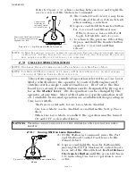
2-11.6 Turning Synchronization ON and OFF when Control Head Levers
are not within a 10% (6 degree) Window of One Another:
The actual synchronizing of the engines occurs when the Con-
trol Head levers are within the 10% (approximately 6 degrees)
window of one another. However, synchronization can be
turned ON or OFF when the Control Head levers are apart more
than the 10% (approximately 6 degrees) window of one another.
Содержание ClearCommand 9000 Series
Страница 1: ...ClearCommand 9000 Series Installation Operation and Troubleshooting Manual MM9000 I Rev C 2 5 08...
Страница 132: ......
Страница 133: ...APPENDIX A...
Страница 134: ......
Страница 139: ......
Страница 140: ...Page A 4...
Страница 143: ......
Страница 144: ...10...
Страница 148: ...Page A 18...
Страница 149: ...Page A 19 TEMPLATE...
Страница 150: ...Page A 20...
Страница 152: ...Page A 22...
Страница 154: ...Page A 24...
Страница 156: ...Page A 26...
Страница 157: ...Page A 27 Drawing 11488D 1 Twin Screw Single APS Connection Alternate Remote Switch...
Страница 158: ...Page A 28...
Страница 159: ...Page A 29 Drawing 11488D 2 Twin Screw Dual APS Connections...
Страница 160: ...Page A 30...
Страница 161: ...Page A 31 Drawing 11488D 3 APS Notes Page...
Страница 162: ...Page A 32...
Страница 164: ...Page A 34...
Страница 166: ...Page A 36...
Страница 170: ...Page A 40...
Страница 172: ...Page A 42...
Страница 176: ...Page A 46...
Страница 178: ...Page C 48 ZF Mathers LLC 12125 Harbour Reach Drive Suite B Mukilteo WA 98275...
Страница 179: ...APPENDIX B...
Страница 180: ......
Страница 234: ...Appendix B 6...
Страница 238: ...Appendix B 10...
Страница 242: ...Appendix B 14...
Страница 247: ...Service Field Test Unit Reference Manual MM13927 Rev E 4 07...
Страница 248: ......
Страница 250: ...Page ii Table of Contents...
Страница 264: ...SERVICE FIELD TEST UNIT MM13927 RvD 10 03 Page 3 2...
Страница 265: ...APPENDIX C...
Страница 266: ......
Страница 267: ...Appendix C 1 Drawing 12284A 1 ClearCommand Diagram all options...
Страница 268: ...Appendix C 2...
Страница 269: ...Appendix C 3 Drawing 12284A 2 ClearCommand Circuit Board Connections...
Страница 270: ...Appendix C 4...
Страница 271: ...Appendix C 5 Drawing 12284A 3 ClearCommand Drawing Notes Page...
Страница 272: ...Appendix C 6...

