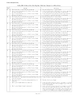
TROUBLESHOOTING
Page B9-5
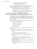
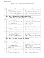
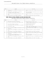
Error
No.
Causes
Solutions
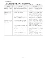
46 a. The Serial Harness is in excess of 120 feet (37m).
a. Reposition the Processor(s) so that the Serial Harness
is less than 120 feet (37m).
b. The Processor is defective.
b. Replace the faulty Processor.
c. The Serial Harness’s shield is not properly terminated. c. Ensure that the shield is terminated and the termina-
tion is at one side only.
47 a. The Serial Harness is in excess of 120 feet (37m).
a. Reposition the Processor(s) so that the Serial Harness
is less than 120 feet (37m).
b. The Processor is defective.
b. Replace the faulty Processor.
c. The Serial Harness’s shield is not properly terminated. c. Ensure that the shield is terminated and the termina-
tion is at one side only.
48 a. The Serial Harness is in excess of 120 feet (37m).
a. Reposition the Processor(s) so that the Serial Harness
is less than 120 feet (37m).
b. The Processor is defective.
b. Replace the faulty Processor.
c. The Serial Harness’s shield is not properly terminated. c. Ensure that the shield is terminated and the termina-
tion is at one side only.
49 a. The Serial Harness is in excess of 120 feet (37m).
a. Reposition the Processor(s) so that the Serial Harness
is less than 120 feet (37m).
b. The Processor is defective.
b. Replace the faulty Processor.
c. The Serial Harness’s shield is not properly terminated. c. Ensure that the shield is terminated and the termina-
tion is at one side only.
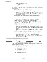
50 a. The Serial Harness is not connected at Processor ID
No.1.
a. Connect the Serial Harness into Processor ID No.1.
b. None of the Processors has ID No. 1 selected.
b. Identify one of the Processors as ID No.1 with the A0
function.
c. Loss of power to Processor ID No.1.
c. Restore power to Processor ID No.1.
51 a. The Serial Harness is not connected at Processor ID
No.2.
a. Connect the Serial Harness into Processor ID No.2.
b. None of the Processors has ID No.2 selected.
b. Identify one of the Processors as ID No.2 with the A0
function.
c. Loss of power to Processor ID No.2
c. Restore power to Processor ID No.2.
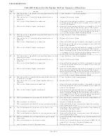
52 a. The Serial Harness is not connected at Processor ID
No.3.
a. Connect the Serial Harness into Processor ID No.3.
b. None of the Processors has ID No.3 selected.
b. Identify one of the Processors as ID No.3 with the A0
function.
c. Loss of power to Processor ID No.3.
c. Restore power to Processor ID No.3.
53 a. The Serial Harness is not connected at Processor ID
No.4.
a. Connect the Serial Harness into Processor ID No.4.
b. None of the Processors has ID No.4 selected.
b. Identify one of the Processors as ID No.4 with the A0
function.
c. Loss of power to Processor ID No.4.
c. Restore power to Processor ID No.4.
54 a. The Serial Harness is not connected at Processor ID
No.5.
a. Connect the Serial Harness into Processor ID No.5.
b. None of the Processors has ID No.5 selected.
b. Identify one of the Processors as ID No.5 with the A0
function.
c. Loss of power to Processor ID No.5.
c. Restore power to Processor ID No.5.
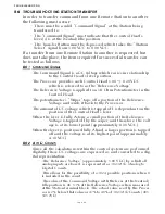
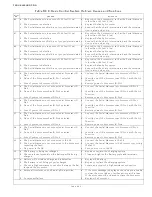
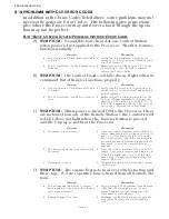
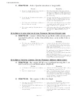
55 a. The Serial Harness is not connected to the SE.
a. Connect the Serial Harness to the SE.
b. The Serial Harness is not connected to the Processor
reporting the fault.
b. Connect the Serial Harness to the Processor reporting
the fault.
c. No power to the SE.
c. Turn power ‘On’ to the SE.
56 a. The battery is being overcharged.
a. Repair or replace the charging system.
b. There’s a loose terminal on the battery while being
charged.
b. Clean and tighten the battery posts and terminals.
57 a. Battery will not take a charge and is defective.
a. Replace the battery.
b. The battery is not being properly charged.
b. Repair or replace the charging system.
c. There’s a high resistance connection between the bat-
tery and the Processor.
c. Locate and repair the high resistance connection.
58 a. External Interference, such as a lightning strike.
a. If the error message is displayed once and you are able
to clear the error, take no further actions at this time.
If the error cannot be cleared, replace the Processor.
b. Component failure.
b. Replace the Processor.
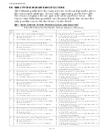
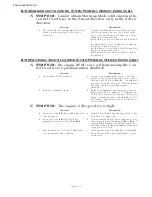
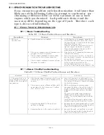
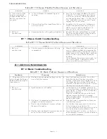
Table B9-9: Basic Control System Problem Causes and Solutions
Содержание ClearCommand 9000 Series
Страница 1: ...ClearCommand 9000 Series Installation Operation and Troubleshooting Manual MM9000 I Rev C 2 5 08...
Страница 132: ......
Страница 133: ...APPENDIX A...
Страница 134: ......
Страница 139: ......
Страница 140: ...Page A 4...
Страница 143: ......
Страница 144: ...10...
Страница 148: ...Page A 18...
Страница 149: ...Page A 19 TEMPLATE...
Страница 150: ...Page A 20...
Страница 152: ...Page A 22...
Страница 154: ...Page A 24...
Страница 156: ...Page A 26...
Страница 157: ...Page A 27 Drawing 11488D 1 Twin Screw Single APS Connection Alternate Remote Switch...
Страница 158: ...Page A 28...
Страница 159: ...Page A 29 Drawing 11488D 2 Twin Screw Dual APS Connections...
Страница 160: ...Page A 30...
Страница 161: ...Page A 31 Drawing 11488D 3 APS Notes Page...
Страница 162: ...Page A 32...
Страница 164: ...Page A 34...
Страница 166: ...Page A 36...
Страница 170: ...Page A 40...
Страница 172: ...Page A 42...
Страница 176: ...Page A 46...
Страница 178: ...Page C 48 ZF Mathers LLC 12125 Harbour Reach Drive Suite B Mukilteo WA 98275...
Страница 179: ...APPENDIX B...
Страница 180: ......
Страница 234: ...Appendix B 6...
Страница 238: ...Appendix B 10...
Страница 242: ...Appendix B 14...
Страница 247: ...Service Field Test Unit Reference Manual MM13927 Rev E 4 07...
Страница 248: ......
Страница 250: ...Page ii Table of Contents...
Страница 264: ...SERVICE FIELD TEST UNIT MM13927 RvD 10 03 Page 3 2...
Страница 265: ...APPENDIX C...
Страница 266: ......
Страница 267: ...Appendix C 1 Drawing 12284A 1 ClearCommand Diagram all options...
Страница 268: ...Appendix C 2...
Страница 269: ...Appendix C 3 Drawing 12284A 2 ClearCommand Circuit Board Connections...
Страница 270: ...Appendix C 4...
Страница 271: ...Appendix C 5 Drawing 12284A 3 ClearCommand Drawing Notes Page...
Страница 272: ...Appendix C 6...

