


INSTALLATION
Page4-14
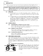
J) Insert the cable ends through the liquid tight connectors
and tighten the nuts.
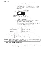
K) Secure the cables internally using a Clamp as shown in
Figure 4-13:, page 4-9. Make certain that the drain wire
makes contact with the Clamp’s metallic surface.
L) Clip the exposed drain wires flush with the Clamps.
M)Connect the conductors to the terminal block as listed in
Table 4-4:.
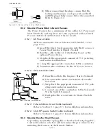
4-4.7 Locations 10 and 11 Installation
4-4.7.1 Clutch Cable (Location 10)
A single four-conductor cable must connect the two Shift
cables to the Processor through a 12 pin plug.
4-4.7.1.1 Processor Termination
A) Install a liquid tight connector into hole no.10.
B) Run a 32 inch (0,82m) piece of four-conductor
cable through the liquid tight connector and
tighten, leaving 16 inches (0,41m) outside of the
Processor.
C) Strip back 4 inches (101,6mm) of the PVC jacket
inside the Processor.
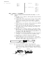
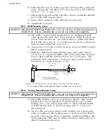
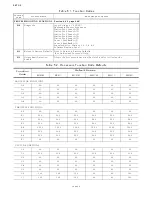
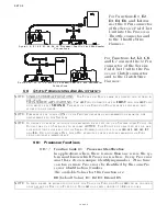
D) Slide a 1 inch (24,5mm) piece of heat shrink over
the end of the cable as shown in Figure 4-20:.
E) Strip back 3/8 inch (9,53mm) from the four con-
ductors and connect to the Processor as shown in
Table 4-5:., page 4-15
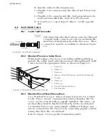
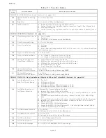
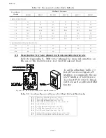
Table 4-4: Processor Circuit Board Terminal Strip Color Coded Connections for Tachometer
Termination
Conductor Color
Description
Notes
TB9-1
Red
Sensor Supply (+9VDC)
Required when Open Collector (i.e., Hall Effect
Sensors) only
TB9-2
Green
AC Type Tachometer Input The green wire connects here when AC Type
Tach Sensors (i.e., Mechanical Senders, Magnetic
Pickup, Alternator AC, etc.) are being used.
TB9-3
Green
Open Collector Tachometer
Input
The green wire connects here when an Open Col-
lector Type Tach Sender is used.
TB9-4
Black
Return for Tachometer
Input
Negative connection for both types of Senders.
Clamp
Silver
Drain wire (Shield) connec-
tion.
Connection made at Processor side only.
Figure 4-20: Clutch Cable Heat Shrink in Processor
Heat Shrink
1 inch
(25,4mm)
4 inches
(101,6mm)
3/8 inch
(9,53mm)
Содержание ClearCommand 9000 Series
Страница 1: ...ClearCommand 9000 Series Installation Operation and Troubleshooting Manual MM9000 I Rev C 2 5 08...
Страница 132: ......
Страница 133: ...APPENDIX A...
Страница 134: ......
Страница 139: ......
Страница 140: ...Page A 4...
Страница 143: ......
Страница 144: ...10...
Страница 148: ...Page A 18...
Страница 149: ...Page A 19 TEMPLATE...
Страница 150: ...Page A 20...
Страница 152: ...Page A 22...
Страница 154: ...Page A 24...
Страница 156: ...Page A 26...
Страница 157: ...Page A 27 Drawing 11488D 1 Twin Screw Single APS Connection Alternate Remote Switch...
Страница 158: ...Page A 28...
Страница 159: ...Page A 29 Drawing 11488D 2 Twin Screw Dual APS Connections...
Страница 160: ...Page A 30...
Страница 161: ...Page A 31 Drawing 11488D 3 APS Notes Page...
Страница 162: ...Page A 32...
Страница 164: ...Page A 34...
Страница 166: ...Page A 36...
Страница 170: ...Page A 40...
Страница 172: ...Page A 42...
Страница 176: ...Page A 46...
Страница 178: ...Page C 48 ZF Mathers LLC 12125 Harbour Reach Drive Suite B Mukilteo WA 98275...
Страница 179: ...APPENDIX B...
Страница 180: ......
Страница 234: ...Appendix B 6...
Страница 238: ...Appendix B 10...
Страница 242: ...Appendix B 14...
Страница 247: ...Service Field Test Unit Reference Manual MM13927 Rev E 4 07...
Страница 248: ......
Страница 250: ...Page ii Table of Contents...
Страница 264: ...SERVICE FIELD TEST UNIT MM13927 RvD 10 03 Page 3 2...
Страница 265: ...APPENDIX C...
Страница 266: ......
Страница 267: ...Appendix C 1 Drawing 12284A 1 ClearCommand Diagram all options...
Страница 268: ...Appendix C 2...
Страница 269: ...Appendix C 3 Drawing 12284A 2 ClearCommand Circuit Board Connections...
Страница 270: ...Appendix C 4...
Страница 271: ...Appendix C 5 Drawing 12284A 3 ClearCommand Drawing Notes Page...
Страница 272: ...Appendix C 6...