


TROUBLESHOOTING
Page B9-1
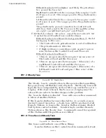
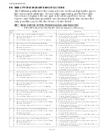
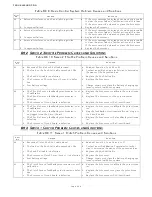
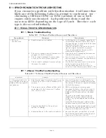
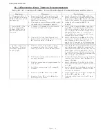
B9 BASIC PROBLEM CAUSES AND SOLUTIONS
The following table lists the various Error Codes and provides possi-
ble causes and solutions. Error Codes appearing on the Port side
Processor’s Display LED are port side errors and vice versa. The
Causes and Solutions provided are the most likely, but are not the
only possible causes for the Errors Codes listed.
B9-1 B
ASIC
C
ONTROL
S
YSTEM
P
ROBLEM
C
AUSES
AND
S
OLUTIONS
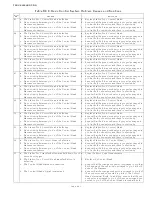
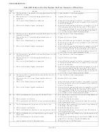
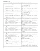
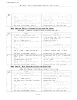
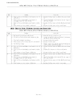
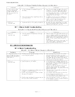
Table B9-9: Basic Control System Problem Causes and Solutions
Error
No.
Causes
Solutions
13 a. Station No.1 Control Head is defective.
a. Replace Station No.1 Control Head.
b. No continuity between pin 5’s of the Control Head
Harness connectors.
b. Ensure that the red conductor is properly crimped to
pin 5 at both connectors.
c. Control Head jumper (pin 3 to 5 or 7) is missing.
c. Install a jumper from pin 3 to 5 on right hand and 3 to 7
on left hand Control Heads.
14 a. The Station No.2 Control Head is defective.
a. Replace Station No.2 Control Head.
b. No continuity between pin 5’s of the Control Head
Harness connectors.
b. Ensure that the red conductor is properly crimped to
pin 5 at both connectors.
c. Control Head jumper (pin 3 to 5 or 7) is missing.
c. Install a jumper from pin 3 to 5 on right hand and 3 to 7
on left hand Control Heads.
15 a. The Station No.3 Control Head is defective.
a. Replace Station No.3 Control Head.
b. No continuity between pin 5’s of the Control Head
Harness connectors.
b. Ensure that the red conductor is properly crimped to
pin 5 at both connectors.
c. Control Head jumper (pin 3 to 5 or 7) is missing.
c. Install a jumper from pin 3 to 5 on right hand and 3 to 7
on left hand Control Heads.
16 a. The Station No.4 Control Head is defective.
a. Replace Station No.4 Control Head.
b. No continuity between pin 5’s of the Control Head
Harness connectors.
b. Ensure that the red conductor is properly crimped to
pin 5 at both connectors.
c. Control Head jumper (pin 3 to 5 or 7) is missing.
c. Install a jumper from pin 3 to 5 on right hand and 3 to 7
on left hand Control Heads.
17 a. The Station No.5 Control Head is defective.
a. Replace Station No.5 Control Head.
b. No continuity between pin 5’s of the Control Head
Harness connectors.
b. Ensure that the red conductor is properly crimped to
pin 5 at both connectors.
c. Control Head jumper (pin 3 to 5 or 7) is missing.
c. Install a jumper from pin 3 to 5 on right hand and 3 to 7
on left hand Control Heads.
18 a. The Station No.6 Control Head is defective.
a. Replace Station No.6 Control Head.
b. No continuity between pin 5’s of the Control Head
Harness connectors.
b. Ensure that the red conductor is properly crimped to
pin 5 at both connectors.
c. Control Head jumper (pin 3 to 5 or 7) is missing.
c. Install a jumper from pin 3 to 5 on right hand and 3 to 7
on left hand Control Heads.
19 a. The Station No.7 Control Head is defective.
a. Replace Station No.7 Control Head.
b. No continuity between pin 5’s of the Control Head
Harness connectors.
b. Ensure that the red conductor is properly crimped to
pin 5 at both connectors.
c. Control Head jumper (pin 3 to 5 or 7) is missing.
c. Install a jumper from pin 3 to 5 on right hand and 3 to 7
on left hand Control Heads.
20 a. The Station No.8 Control Head is defective.
a. Replace Station No.8 Control Head.
b. No continuity between pin 5’s of the Control Head
Harness connectors.
b. Ensure that the red conductor is properly crimped to
pin 5 at both connectors.
c. Control Head jumper (pin 3 to 5 or 7) is missing.
c. Install a jumper from pin 3 to 5 on right hand and 3 to 7
on left hand Control Heads.
21 a. The Station No.9 Control Head is defective.
a. Replace Station No.9 Control Head.
b. No continuity between pin 5’s of the Control Head
Harness connectors.
b. Ensure that the red conductor is properly crimped to
pin 5 at both connectors.
c. Control Head jumper (pin 3 to 5 or 7) is missing.
c. Install a jumper from pin 3 to 5 on right hand and 3 to 7
on left hand Control Heads.
22 a. The Station No.10 Control Head is defective.
a. Replace Station No.10 Control Head.
b. No continuity between pin 5’s of the Control Head
Harness connectors.
b. Ensure that the red conductor is properly crimped to
pin 5 at both connectors.
c. Control Head jumper (pin 3 to 5 or 7) is missing.
c. Install a jumper from pin 3 to 5 on right hand and 3 to 7
on left hand Control Heads.
Содержание ClearCommand 9000 Series
Страница 1: ...ClearCommand 9000 Series Installation Operation and Troubleshooting Manual MM9000 I Rev C 2 5 08...
Страница 132: ......
Страница 133: ...APPENDIX A...
Страница 134: ......
Страница 139: ......
Страница 140: ...Page A 4...
Страница 143: ......
Страница 144: ...10...
Страница 148: ...Page A 18...
Страница 149: ...Page A 19 TEMPLATE...
Страница 150: ...Page A 20...
Страница 152: ...Page A 22...
Страница 154: ...Page A 24...
Страница 156: ...Page A 26...
Страница 157: ...Page A 27 Drawing 11488D 1 Twin Screw Single APS Connection Alternate Remote Switch...
Страница 158: ...Page A 28...
Страница 159: ...Page A 29 Drawing 11488D 2 Twin Screw Dual APS Connections...
Страница 160: ...Page A 30...
Страница 161: ...Page A 31 Drawing 11488D 3 APS Notes Page...
Страница 162: ...Page A 32...
Страница 164: ...Page A 34...
Страница 166: ...Page A 36...
Страница 170: ...Page A 40...
Страница 172: ...Page A 42...
Страница 176: ...Page A 46...
Страница 178: ...Page C 48 ZF Mathers LLC 12125 Harbour Reach Drive Suite B Mukilteo WA 98275...
Страница 179: ...APPENDIX B...
Страница 180: ......
Страница 234: ...Appendix B 6...
Страница 238: ...Appendix B 10...
Страница 242: ...Appendix B 14...
Страница 247: ...Service Field Test Unit Reference Manual MM13927 Rev E 4 07...
Страница 248: ......
Страница 250: ...Page ii Table of Contents...
Страница 264: ...SERVICE FIELD TEST UNIT MM13927 RvD 10 03 Page 3 2...
Страница 265: ...APPENDIX C...
Страница 266: ......
Страница 267: ...Appendix C 1 Drawing 12284A 1 ClearCommand Diagram all options...
Страница 268: ...Appendix C 2...
Страница 269: ...Appendix C 3 Drawing 12284A 2 ClearCommand Circuit Board Connections...
Страница 270: ...Appendix C 4...
Страница 271: ...Appendix C 5 Drawing 12284A 3 ClearCommand Drawing Notes Page...
Страница 272: ...Appendix C 6...