OPERATION
Page 2-19
2-16.2 ClearCommand 9000 Series Pluggable Processors
The 9000 Series Processors come from the factory with standard
five Pigtail Connectors listed in Section 2-15.1, page 2-48, and
additional Pigtails depending on the Processor’s features. Refer
below to the Processor being used on this System for the list of
additional pigtails.
9120
and
9121
Processors
• One pigtail connector is provided for clutch Ahead and Astern
Solenoid signals.
9122
Processor
• One pigtail connector is provided for clutch Ahead and Astern
Solenoid signals, the troll solenoids.
9210
and
9211
Processors
• One pigtail connector is provided for electronic connection to the
engine governor.
9221
Processor
• One pigtail connector is provided for electronic connection to the
engine governor.
• One pigtail connector is provided for clutch Ahead and Astern
Solenoid signals.
2-17 O
PTIONAL
F
EATURES
O
PERATION
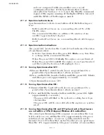
2-17.1 System Failure External Alarm
• This optional feature is designed to provide a status signal to
an external alarm circuit.
• The status signal is in the form of an open or closed contact.
When the contact is closed, the Processor is functioning nor-
mally. When the contact opens, this indicates the software
program has quit running due to a component failure or loss
of DC power.
• A full explanation is provided in Section 8-1, page 8-1.
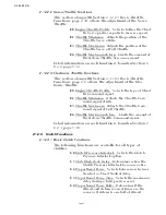
2-17.2 Clutch Pressure Interlock
• The purpose of the Clutch Pressure Interlock is to prevent
high engine RPM when the Clutch is not fully engaged.
• A full explanation of the Clutch Pressure Interlock is provided
in Section 8-2, page 8-2.
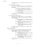
2-17.3 Station Expander (SE)
• The SE is a separate Processor housed in an enclosure that
allows the connection of up to five additional Remote Control
Stations.
• The SE communicates with the Processor over the serial com-
munication line.
• A full explanation of the installation, operation and adjust-
ment of the SE is provided in the Installation Manual provided
with the SE.
• Additional information can be found in Section 8-3, page 8-4.
Содержание ClearCommand 9000 Series
Страница 1: ...ClearCommand 9000 Series Installation Operation and Troubleshooting Manual MM9000 I Rev C 2 5 08...
Страница 132: ......
Страница 133: ...APPENDIX A...
Страница 134: ......
Страница 139: ......
Страница 140: ...Page A 4...
Страница 143: ......
Страница 144: ...10...
Страница 148: ...Page A 18...
Страница 149: ...Page A 19 TEMPLATE...
Страница 150: ...Page A 20...
Страница 152: ...Page A 22...
Страница 154: ...Page A 24...
Страница 156: ...Page A 26...
Страница 157: ...Page A 27 Drawing 11488D 1 Twin Screw Single APS Connection Alternate Remote Switch...
Страница 158: ...Page A 28...
Страница 159: ...Page A 29 Drawing 11488D 2 Twin Screw Dual APS Connections...
Страница 160: ...Page A 30...
Страница 161: ...Page A 31 Drawing 11488D 3 APS Notes Page...
Страница 162: ...Page A 32...
Страница 164: ...Page A 34...
Страница 166: ...Page A 36...
Страница 170: ...Page A 40...
Страница 172: ...Page A 42...
Страница 176: ...Page A 46...
Страница 178: ...Page C 48 ZF Mathers LLC 12125 Harbour Reach Drive Suite B Mukilteo WA 98275...
Страница 179: ...APPENDIX B...
Страница 180: ......
Страница 234: ...Appendix B 6...
Страница 238: ...Appendix B 10...
Страница 242: ...Appendix B 14...
Страница 247: ...Service Field Test Unit Reference Manual MM13927 Rev E 4 07...
Страница 248: ......
Страница 250: ...Page ii Table of Contents...
Страница 264: ...SERVICE FIELD TEST UNIT MM13927 RvD 10 03 Page 3 2...
Страница 265: ...APPENDIX C...
Страница 266: ......
Страница 267: ...Appendix C 1 Drawing 12284A 1 ClearCommand Diagram all options...
Страница 268: ...Appendix C 2...
Страница 269: ...Appendix C 3 Drawing 12284A 2 ClearCommand Circuit Board Connections...
Страница 270: ...Appendix C 4...
Страница 271: ...Appendix C 5 Drawing 12284A 3 ClearCommand Drawing Notes Page...
Страница 272: ...Appendix C 6...

