


TROUBLESHOOTING
Page B13-2
B13-2C
LUTCH
P
IGTAIL
B13-3C
LUTCH
/T
ROLL
P
IGTAIL
B13-4T
HROTTLE
P
IGTAIL
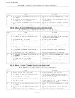
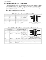
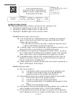
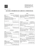
Table B13-4: Clutch Pigtail Pin-Out
CIRCUIT BOARD
PLUG
Figure B13-4: Clutch Pigtail Pin Out
Termination A Conductor Color Termination B
Description
TB11-1
Black
Pin 5
Astern Clutch (+)
TB11-2
Brown
Pin 3
Ahead Clutch (+)
TB11-5
Yellow
Pin 6
Astern clutch ( - )
TB11-6
Green
Pin 4
Ahead Clutch ( - )
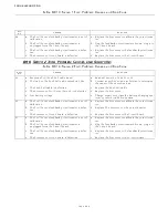
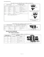
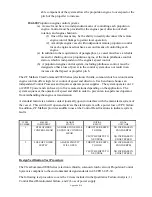
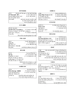
Table B13-5: Clutch/Troll Pigtail Pin-Out
CIRCUIT BOARD
PLUG
Figure B13-5: Clutch/Troll Pigtail Pin
Out
Termination A Conductor Color Termination B
Description
TB11-1
Black
Pin 5
Astern Clutch (+)
TB11-2
Brown
Pin 3
Ahead Clutch (+)
TB11-3
Red
Pin 11
Troll Proportional
Solenoid (+)
TB11-4
Orange
Pin 9
Troll On/Off (+)
TB11-5
Yellow
Pin 6
Astern clutch ( - )
TB11-6
Green
Pin 4
Ahead Clutch ( - )
TB11-7
Blue
Pin 12
Troll Proportional Solenoid ( - )
TB11-8
White
Pin 10
Troll On/Off
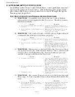
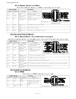
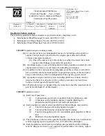
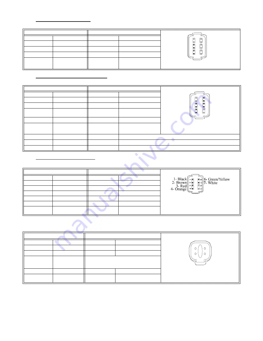
Table B13-6: Throttle Pigtail Pin-Out
CIRCUIT BOARD
PLUG
Figure B13-6: Throttle Pigtail Pin Out
Termination A Conductor Color Termination B
Description
TB8-3
Brown
Pin 2
PWM (+)
TB8-4
Red
Pin 3
Current (+)
TB8-5
Orange
Pin 4
VDC (+)
TB8-6
White
Pin 7
Frequency (+)
TB8-7
Black
Pin 1
Signal Ground
P-Clamp to
Frame
Green/Yellow
Pin 8
Shield
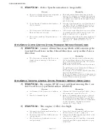
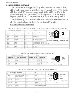
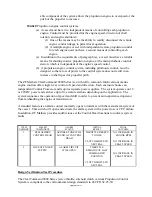
Table B13-7: Tachometer Sensor Pigtail Pin-Out
CIRCUIT BOARD
PLUG
Figure B13-7: Tachometer Sensor No.1
Pigtail Pin Out
Termination A Conductor Color Termination B
Description
TB9- 1
Red
Pin 1
Sensor Supply (+9VDC)
TB9- 2
Green
Pin 2
AC Type Tach Input
TB9- 3
N/C
Open Collector Tach Input (the green
wire is moved from TB9-2 to TB9-3 when
an Open Collector Tach is used)
TB9- 4
Black
Pin 3
Return for Tach Input
Grounding
Screw
Drain
Pin 4
Shield
1
2
3
4
5
6
7
8
9
1
0
11
1
2
3 - Brown
4 - Green
5 - Black
6 - Yellow
1
2
3
4
5
6
7
8
9
1
0
11
1
2
3 - Brown
4 - Green
5 - Black
6 - Yellow
12 - Blue
11 - Red
10 - White
9- Orange
1
2
4
3
2 - Green
1 - Red
3 - Black
4 - Shield/
Drain
Содержание ClearCommand 9000 Series
Страница 1: ...ClearCommand 9000 Series Installation Operation and Troubleshooting Manual MM9000 I Rev C 2 5 08...
Страница 132: ......
Страница 133: ...APPENDIX A...
Страница 134: ......
Страница 139: ......
Страница 140: ...Page A 4...
Страница 143: ......
Страница 144: ...10...
Страница 148: ...Page A 18...
Страница 149: ...Page A 19 TEMPLATE...
Страница 150: ...Page A 20...
Страница 152: ...Page A 22...
Страница 154: ...Page A 24...
Страница 156: ...Page A 26...
Страница 157: ...Page A 27 Drawing 11488D 1 Twin Screw Single APS Connection Alternate Remote Switch...
Страница 158: ...Page A 28...
Страница 159: ...Page A 29 Drawing 11488D 2 Twin Screw Dual APS Connections...
Страница 160: ...Page A 30...
Страница 161: ...Page A 31 Drawing 11488D 3 APS Notes Page...
Страница 162: ...Page A 32...
Страница 164: ...Page A 34...
Страница 166: ...Page A 36...
Страница 170: ...Page A 40...
Страница 172: ...Page A 42...
Страница 176: ...Page A 46...
Страница 178: ...Page C 48 ZF Mathers LLC 12125 Harbour Reach Drive Suite B Mukilteo WA 98275...
Страница 179: ...APPENDIX B...
Страница 180: ......
Страница 234: ...Appendix B 6...
Страница 238: ...Appendix B 10...
Страница 242: ...Appendix B 14...
Страница 247: ...Service Field Test Unit Reference Manual MM13927 Rev E 4 07...
Страница 248: ......
Страница 250: ...Page ii Table of Contents...
Страница 264: ...SERVICE FIELD TEST UNIT MM13927 RvD 10 03 Page 3 2...
Страница 265: ...APPENDIX C...
Страница 266: ......
Страница 267: ...Appendix C 1 Drawing 12284A 1 ClearCommand Diagram all options...
Страница 268: ...Appendix C 2...
Страница 269: ...Appendix C 3 Drawing 12284A 2 ClearCommand Circuit Board Connections...
Страница 270: ...Appendix C 4...
Страница 271: ...Appendix C 5 Drawing 12284A 3 ClearCommand Drawing Notes Page...
Страница 272: ...Appendix C 6...