


Page A-16
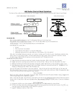
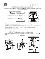
MOUNTING AND INSTALLATION:
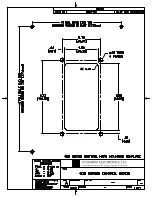
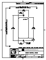
Select the desired mounting locations and drill screw and cable holes as indi-
cated on the template diagram. Refer to the Dimensions Diagram on the next
page.
Run cable/harnesses between Processor and Control Head. Label both ends
with the Station it connects
(EXAMPLE: Port, Center, or Starboard; Port Thrust, Port
Throttle; etc.)
There are two types of Control Head connections available: Plug or Terminal
Connected. Both types may be used with MicroCommander, ClearCommand, or
CruiseCommand using the appropriate cable or harness. Follow the appropriate
steps for the Control Head that has been supplied for your system.
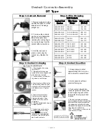
Standard Cable
Remove the six screws holding the bottom cover of the
Control Head housings and set aside.
Insert cable through the correct cable grip in the bottom
cover.
Strip back the PVC cover on the shielded cable approxi-
mately 2-1/2"
(63,5mm)
at the Control Head.
At the Control Head end of the cable strip and cut off the
shielding and drain wire flush with the end of the PVC
cover (the drain wire at the Control Head is not connected
to ground).
Strip 3/8"
(9,5mm)
insulation off each wire.
Twist the individual strands of the wires to minimize fray-
ing.
Crimp a locking fork terminal (included with each Control
Head) to each of the conductors.
Make connections to the Control Head as indicated in the
following TERMINAL CONNECTIONS diagrams.
Pluggable
Plug Control Head cable
into the pigtail at the
Control Head.
(Ensure the
correct Processor Cable is
being plugged into the corre-
sponding Control Head lever
pigtail)
.
When connecting the
plugs, ensure that the
release button or but-
tons are depressed and
held until plug is fully
connected or discon-
nected. Connecting or
disconnecting plugs
without depressing and
holding the release but-
ton or buttons will dam-
age the plug.
ALWAYS REFER TO THE MANUAL THAT IS
SUPPLIED WITH THE CONTROL SYSTEM
FOR ANY UNIQUE CONTROL HEAD CON-
NECTIONS FOR YOUR SYSTEM.
When cable connections are complete:
Replace Control Head bottom cover using
the six (6) mounting screws removed ear-
lier. Ensure seal is in place.
Tighten watertight cable grip(s).
Remove front cover from the Control Head
Mount Control Head with supplied hard-
ware.
Replace front cover when mounting is com-
plete.
Содержание ClearCommand 9000 Series
Страница 1: ...ClearCommand 9000 Series Installation Operation and Troubleshooting Manual MM9000 I Rev C 2 5 08...
Страница 132: ......
Страница 133: ...APPENDIX A...
Страница 134: ......
Страница 139: ......
Страница 140: ...Page A 4...
Страница 143: ......
Страница 144: ...10...
Страница 148: ...Page A 18...
Страница 149: ...Page A 19 TEMPLATE...
Страница 150: ...Page A 20...
Страница 152: ...Page A 22...
Страница 154: ...Page A 24...
Страница 156: ...Page A 26...
Страница 157: ...Page A 27 Drawing 11488D 1 Twin Screw Single APS Connection Alternate Remote Switch...
Страница 158: ...Page A 28...
Страница 159: ...Page A 29 Drawing 11488D 2 Twin Screw Dual APS Connections...
Страница 160: ...Page A 30...
Страница 161: ...Page A 31 Drawing 11488D 3 APS Notes Page...
Страница 162: ...Page A 32...
Страница 164: ...Page A 34...
Страница 166: ...Page A 36...
Страница 170: ...Page A 40...
Страница 172: ...Page A 42...
Страница 176: ...Page A 46...
Страница 178: ...Page C 48 ZF Mathers LLC 12125 Harbour Reach Drive Suite B Mukilteo WA 98275...
Страница 179: ...APPENDIX B...
Страница 180: ......
Страница 234: ...Appendix B 6...
Страница 238: ...Appendix B 10...
Страница 242: ...Appendix B 14...
Страница 247: ...Service Field Test Unit Reference Manual MM13927 Rev E 4 07...
Страница 248: ......
Страница 250: ...Page ii Table of Contents...
Страница 264: ...SERVICE FIELD TEST UNIT MM13927 RvD 10 03 Page 3 2...
Страница 265: ...APPENDIX C...
Страница 266: ......
Страница 267: ...Appendix C 1 Drawing 12284A 1 ClearCommand Diagram all options...
Страница 268: ...Appendix C 2...
Страница 269: ...Appendix C 3 Drawing 12284A 2 ClearCommand Circuit Board Connections...
Страница 270: ...Appendix C 4...
Страница 271: ...Appendix C 5 Drawing 12284A 3 ClearCommand Drawing Notes Page...
Страница 272: ...Appendix C 6...