


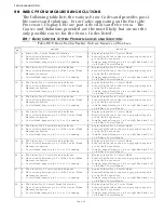


TROUBLESHOOTING
Page B10-2
E)
SYMPTOM:
Active Synchronization is inoperable.
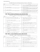
B10-2S
ERVO
C
LUTCH
C
ONTROL
S
YSTEM
P
ROBLEMS
W
ITHOUT
E
RROR
C
ODES
A)
SYMPTOM:
Cannot obtain Warm-up Mode while moving the
Control Head lever in the Ahead direction, only in the Astern
direction.
B10-3S
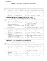
ERVO
T
HROTTLE
C
ONTROL
S
YSTEM
P
ROBLEMS
W
ITHOUT
E
RROR
C
ODES
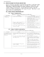
A)
SYMPTOM:
The engine RPM’s vary, without moving the Con-
trol Head lever (synchronization disabled).
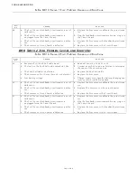
B)
SYMPTOM:
The engine’s Idle is too high.
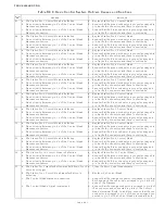
Cause
Remedy
a. There is no Tachometer Sensor signal at
the Port or Starboard Processor.
a. The Tachometer Sensor frequency can be
seen on the Processor’s Display by accessing
the Diagnostic Menu H0. If the frequency is
not measured, check the Tachometer Sensor
and the wiring.
b. Loss of Serial Communication between
the Processors.
b. If Active Synchronization is inoperative due
to a lack of Serial Communications, one or
more Error Codes will be displayed indicat-
ing the loss of communication.
c. The Processor’s Identification number(s)
have not been set properly.
c. All Processors must have a unique identifica-
tion number as set with Function Code A0.
Refer to Section 5-6.1.1., page 5-8.
d. The correct number of engines has not
been set.
d. All Processor must have the same number of
engines selected as programmed with Func-
tion Code A1. Refer to Section 5-6.1.2.,
page 5-9.
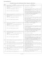
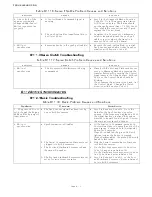
Cause
Remedy
a. The Processor is sensing that the Control
Head’s lever is moving in the Astern
direction
Depress the Transfer Button while moving
the Control Head lever in the Astern direc-
tion. If the LED begins to blink, the Control
Head is incorrectly wired.
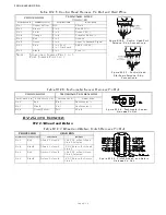
•
Check the colors of the wires at pins 5 and
7.
•
A right hand Control Head should have yel-
low at pin 5 and blue at pin 7.
•
A left hand Control Head should have blue
at pin 5 and yellow at pin 7.
•
The Clutch Servo’s direction of travel must
be changed with Function Code C5 if the yel-
low and blue wires are reversed.
Cause
Remedy
a. Problem with the Governor or Carbure-
tor.
a. Observe the Throttle push-pull cable. If vari-
ations are seen, proceed to Step b.
b. Erratic Command Signal.
b. Refer to Command Signal testing in Section
B6-1 and Section B6-2, page B6-1. If varia-
tions of the A/D counts occur, connect the
Control Head to another Station (if available)
on the Processor. If variations persist,
replace the Control Head.
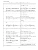
Cause
Remedy
a. Idle was not adjusted mechanically cor-
rect at the Idle stop.
a. Adjust the Throttle Push-Pull cable as speci-
fied in Section 5-6.2.2.1., page 5-16.
b. Function Code E2 Throttle Minimum is
incorrectly set.
b. Adjust Throttle Minimum as specified in Sec-
tion 5-6.2.2.2, page 5-17.
c. The Governor or Carburetor is incor-
rectly adjusted.
c. After Causes a. and b. have been eliminated,
contact a certified engine mechanic to prop-
erly adjust.
Содержание ClearCommand 9000 Series
Страница 1: ...ClearCommand 9000 Series Installation Operation and Troubleshooting Manual MM9000 I Rev C 2 5 08...
Страница 132: ......
Страница 133: ...APPENDIX A...
Страница 134: ......
Страница 139: ......
Страница 140: ...Page A 4...
Страница 143: ......
Страница 144: ...10...
Страница 148: ...Page A 18...
Страница 149: ...Page A 19 TEMPLATE...
Страница 150: ...Page A 20...
Страница 152: ...Page A 22...
Страница 154: ...Page A 24...
Страница 156: ...Page A 26...
Страница 157: ...Page A 27 Drawing 11488D 1 Twin Screw Single APS Connection Alternate Remote Switch...
Страница 158: ...Page A 28...
Страница 159: ...Page A 29 Drawing 11488D 2 Twin Screw Dual APS Connections...
Страница 160: ...Page A 30...
Страница 161: ...Page A 31 Drawing 11488D 3 APS Notes Page...
Страница 162: ...Page A 32...
Страница 164: ...Page A 34...
Страница 166: ...Page A 36...
Страница 170: ...Page A 40...
Страница 172: ...Page A 42...
Страница 176: ...Page A 46...
Страница 178: ...Page C 48 ZF Mathers LLC 12125 Harbour Reach Drive Suite B Mukilteo WA 98275...
Страница 179: ...APPENDIX B...
Страница 180: ......
Страница 234: ...Appendix B 6...
Страница 238: ...Appendix B 10...
Страница 242: ...Appendix B 14...
Страница 247: ...Service Field Test Unit Reference Manual MM13927 Rev E 4 07...
Страница 248: ......
Страница 250: ...Page ii Table of Contents...
Страница 264: ...SERVICE FIELD TEST UNIT MM13927 RvD 10 03 Page 3 2...
Страница 265: ...APPENDIX C...
Страница 266: ......
Страница 267: ...Appendix C 1 Drawing 12284A 1 ClearCommand Diagram all options...
Страница 268: ...Appendix C 2...
Страница 269: ...Appendix C 3 Drawing 12284A 2 ClearCommand Circuit Board Connections...
Страница 270: ...Appendix C 4...
Страница 271: ...Appendix C 5 Drawing 12284A 3 ClearCommand Drawing Notes Page...
Страница 272: ...Appendix C 6...