


INSTALLATION
Page4-13
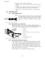
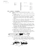
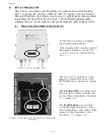
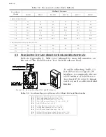
4-4.6.5 Tachometer Cable (Location 9)
A) Run a two- or three-conductor shielded cable from the
Port Processor to the Port engine’s tachometer source.
(Refer to Section 3-1.5, page 3-6)
B) Run a two- or three-conductor shielded cable from the
Starboard Processor to the Starboard engine’s tachome-
ter source.
C) Install a 1/2 inch (12,7mm) liquid tight cable grip into
hole (No. 9) of the Port and Starboard Processors. (Refer
to Figure 4-5:, page 4-10, for entry hole location and Fig-
ure 4-4:, page 4-10, for cable grip installation)
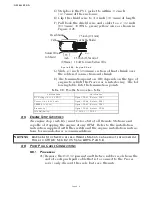
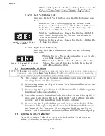
D) Strip back 2 inches (50,8mm) of PVC jacketing from
both ends of the cable.
E) Strip the ends of each conductor back 3/8 inch (9,5mm).
F) Clip off the drain wire flush with the PVC jacketing at
the Tachometer source side only.
G) Place a 7/8 inch (22,23mm) section of shrink tubing over
each end of the cable.
H) At the Processor side, bend the drain wire back and
tuck it under the shrink tubing so that the grain wire
end is exposed past the shrink tubing. (Refer to Figure 4-
18: and Figure 4-19:).
.
I) Shrink the tubing with a heat gun.
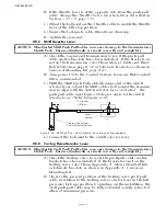
TB7-9
Black
TB7-9
Clamp
Silver (Drain Wire)
No Connection
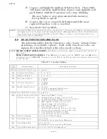
NOTE: T
HREE
-
CONDUCTOR
CABLE
IS
REQUIRED
WITH
O
PEN
C
OLLECTOR
T
YPE
(H
ALL
E
FFECT
) T
ACHOM
-
ETER
S
ENDERS
ONLY
.
Figure 4-18: AC Type Tachometer Cable
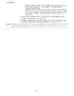
Figure 4-19: Open Collector Tachometer Cable
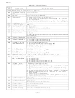
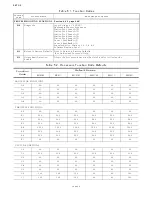
Table 4-3: Processor Circuit Board Terminal Strip Color Coded Connections for Serial
Communication
PORT PROCESSOR
Conductor Color
STARBOARD PROCESSOR
Termination A
Termination B
Heat Shrink
1 inch
(25,4mm)
3.5 inches
(88,9mm)
3/8 inch
(9,53mm)
Wrapped Drain Wire
Clip Drain Wire
1 inch
(25,4mm)
3.5 inches
(88,9mm)
3/8 inch
(9,53mm)
PROCESSOR
TACHOMETER SENDER
Heat Shrink
1 inch
(25,4mm)
3.5 inches
(88,9mm)
3/8 inch
(9,53mm)
Wrapped Drain Wire
Clip Drain Wire
1 inch
(25,4mm)
3.5 inches
(88,9mm)
3/8 inch
(9,53mm)
PROCESSOR
TACHOMETER SENDER
Содержание ClearCommand 9000 Series
Страница 1: ...ClearCommand 9000 Series Installation Operation and Troubleshooting Manual MM9000 I Rev C 2 5 08...
Страница 132: ......
Страница 133: ...APPENDIX A...
Страница 134: ......
Страница 139: ......
Страница 140: ...Page A 4...
Страница 143: ......
Страница 144: ...10...
Страница 148: ...Page A 18...
Страница 149: ...Page A 19 TEMPLATE...
Страница 150: ...Page A 20...
Страница 152: ...Page A 22...
Страница 154: ...Page A 24...
Страница 156: ...Page A 26...
Страница 157: ...Page A 27 Drawing 11488D 1 Twin Screw Single APS Connection Alternate Remote Switch...
Страница 158: ...Page A 28...
Страница 159: ...Page A 29 Drawing 11488D 2 Twin Screw Dual APS Connections...
Страница 160: ...Page A 30...
Страница 161: ...Page A 31 Drawing 11488D 3 APS Notes Page...
Страница 162: ...Page A 32...
Страница 164: ...Page A 34...
Страница 166: ...Page A 36...
Страница 170: ...Page A 40...
Страница 172: ...Page A 42...
Страница 176: ...Page A 46...
Страница 178: ...Page C 48 ZF Mathers LLC 12125 Harbour Reach Drive Suite B Mukilteo WA 98275...
Страница 179: ...APPENDIX B...
Страница 180: ......
Страница 234: ...Appendix B 6...
Страница 238: ...Appendix B 10...
Страница 242: ...Appendix B 14...
Страница 247: ...Service Field Test Unit Reference Manual MM13927 Rev E 4 07...
Страница 248: ......
Страница 250: ...Page ii Table of Contents...
Страница 264: ...SERVICE FIELD TEST UNIT MM13927 RvD 10 03 Page 3 2...
Страница 265: ...APPENDIX C...
Страница 266: ......
Страница 267: ...Appendix C 1 Drawing 12284A 1 ClearCommand Diagram all options...
Страница 268: ...Appendix C 2...
Страница 269: ...Appendix C 3 Drawing 12284A 2 ClearCommand Circuit Board Connections...
Страница 270: ...Appendix C 4...
Страница 271: ...Appendix C 5 Drawing 12284A 3 ClearCommand Drawing Notes Page...
Страница 272: ...Appendix C 6...