


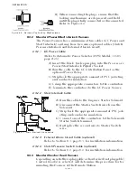


PLAN THE INSTALLATION
Page3-1
3
PLAN THE INSTALLATION
3-1 S
YSTEM
R
EQUIREMENTS
The first step when installing a System is to carefully plan the
installation. This includes finding proper mounting locations for
the Processor(s) and Control Heads. The decision must be made
on where power is going to be sourced and how the power will be
routed to the Processor(s). Once the locations have been decided,
lengths of electrical wiring, Harnesses and push-pull cables must
be determined.
• Bonding is required for maximum electromagnetic compatibility
(EMC) performance. Refer to Bonding: A.B.Y.C. E-11, 46 CFR
111.05, page A-33
• Locate the Processor such that the push-pull cables have the short-
est, most direct path to the selector lever. The push-pull cable
length should not exceed 20 feet (6,0m), the bend radius should
not be less than 10 inches (254mm) and the total degrees of bends
must be less than 270 degrees.
Only when the previous items have been completed, should you
start the actual installation. The following sections describe the
requirements for installing the components and selecting mounting
locations.
NOTE: ZF M
ATHERS
RECOMMENDS
THAT
THE
SYSTEM
BE
INSTALLED
IN
ACCORDANCE
WITH
ABYC, E-
11
AND
P24.
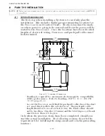
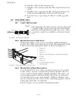
Figure 3-1: Processor Dimensions
4.75
(120,7mm)
3.20
(81,3mm)
10.25
(260,4mm)
10.40
(264,2mm)
6.70
(170,2mm)
2.69
(68,3mm)
10.71
(272mm)
2.70
(68,6mm)
12256-
Содержание ClearCommand 9000 Series
Страница 1: ...ClearCommand 9000 Series Installation Operation and Troubleshooting Manual MM9000 I Rev C 2 5 08...
Страница 132: ......
Страница 133: ...APPENDIX A...
Страница 134: ......
Страница 139: ......
Страница 140: ...Page A 4...
Страница 143: ......
Страница 144: ...10...
Страница 148: ...Page A 18...
Страница 149: ...Page A 19 TEMPLATE...
Страница 150: ...Page A 20...
Страница 152: ...Page A 22...
Страница 154: ...Page A 24...
Страница 156: ...Page A 26...
Страница 157: ...Page A 27 Drawing 11488D 1 Twin Screw Single APS Connection Alternate Remote Switch...
Страница 158: ...Page A 28...
Страница 159: ...Page A 29 Drawing 11488D 2 Twin Screw Dual APS Connections...
Страница 160: ...Page A 30...
Страница 161: ...Page A 31 Drawing 11488D 3 APS Notes Page...
Страница 162: ...Page A 32...
Страница 164: ...Page A 34...
Страница 166: ...Page A 36...
Страница 170: ...Page A 40...
Страница 172: ...Page A 42...
Страница 176: ...Page A 46...
Страница 178: ...Page C 48 ZF Mathers LLC 12125 Harbour Reach Drive Suite B Mukilteo WA 98275...
Страница 179: ...APPENDIX B...
Страница 180: ......
Страница 234: ...Appendix B 6...
Страница 238: ...Appendix B 10...
Страница 242: ...Appendix B 14...
Страница 247: ...Service Field Test Unit Reference Manual MM13927 Rev E 4 07...
Страница 248: ......
Страница 250: ...Page ii Table of Contents...
Страница 264: ...SERVICE FIELD TEST UNIT MM13927 RvD 10 03 Page 3 2...
Страница 265: ...APPENDIX C...
Страница 266: ......
Страница 267: ...Appendix C 1 Drawing 12284A 1 ClearCommand Diagram all options...
Страница 268: ...Appendix C 2...
Страница 269: ...Appendix C 3 Drawing 12284A 2 ClearCommand Circuit Board Connections...
Страница 270: ...Appendix C 4...
Страница 271: ...Appendix C 5 Drawing 12284A 3 ClearCommand Drawing Notes Page...
Страница 272: ...Appendix C 6...