


OPERATION
Page 2-10
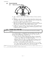
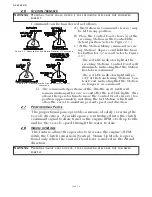
• When synchronization is turned ON by pressing the transfer but-
ton, the green LED will light after two seconds and stay lighted as
long as the transfer button is depressed.
• When turning OFF synchronization by pressing the transfer but-
ton for two seconds, the green LED will blink twice indicating
that synchronization is turned OFF.
2-12 C
ONTROL
S
YSTEM
’
S
C
ONFIGURABILITY
The Processor is designed in a way which allows it to be easily
configured by the installer to meet the varying needs of a wide
variety of vessels. Below you will find a list and a brief descrip-
tion of the groups of these functions.
2-12.1 Processor Functions
Within this section of adjustable parameters, there are up to
five different adjustments:
A0 Processor Identification - Assigns each Processor in
multi-screw application a unique identifying number.
This function must be the second function set dur-
ing Set Up.
A1 Number of Engines - Lets the Processor know how
many other Processors need to be communicated
with. This function must be the first function set
during Set Up.
A2 One Lever Operation - Allows the installer to disable or
enable One Lever Mode capability.
A3 Station Expander - Allows the Processor to communi-
cate with the Station Expander (SE).
A4 Neutral Indication Tone - When turned ON, produces a
short 50 Hz tone to indicate Neutral.
Detail information on each function is found in Section 5-6.1,
page 5-8.
2-12.2 Throttle Functions
2-12.2.1 Basic Throttle Functions
This section allows the adjustment of the Throttle:
E1
Throttle in Neutral
-
Adjusts the position of the
Throttle while in Neutral
E5
Throttle Pause following Shift
-
Allows a pause
prior to applying speed above Idle.
E6
High Idle
-
Programs a second elevated Idle RPM.
E7
Synchronization
-
Allows the installer to select
synchronization and select the type of syn-
chronization.
Detail information on each function is found in Section 5-
6.2.1, page 5-10.
Содержание ClearCommand 9000 Series
Страница 1: ...ClearCommand 9000 Series Installation Operation and Troubleshooting Manual MM9000 I Rev C 2 5 08...
Страница 132: ......
Страница 133: ...APPENDIX A...
Страница 134: ......
Страница 139: ......
Страница 140: ...Page A 4...
Страница 143: ......
Страница 144: ...10...
Страница 148: ...Page A 18...
Страница 149: ...Page A 19 TEMPLATE...
Страница 150: ...Page A 20...
Страница 152: ...Page A 22...
Страница 154: ...Page A 24...
Страница 156: ...Page A 26...
Страница 157: ...Page A 27 Drawing 11488D 1 Twin Screw Single APS Connection Alternate Remote Switch...
Страница 158: ...Page A 28...
Страница 159: ...Page A 29 Drawing 11488D 2 Twin Screw Dual APS Connections...
Страница 160: ...Page A 30...
Страница 161: ...Page A 31 Drawing 11488D 3 APS Notes Page...
Страница 162: ...Page A 32...
Страница 164: ...Page A 34...
Страница 166: ...Page A 36...
Страница 170: ...Page A 40...
Страница 172: ...Page A 42...
Страница 176: ...Page A 46...
Страница 178: ...Page C 48 ZF Mathers LLC 12125 Harbour Reach Drive Suite B Mukilteo WA 98275...
Страница 179: ...APPENDIX B...
Страница 180: ......
Страница 234: ...Appendix B 6...
Страница 238: ...Appendix B 10...
Страница 242: ...Appendix B 14...
Страница 247: ...Service Field Test Unit Reference Manual MM13927 Rev E 4 07...
Страница 248: ......
Страница 250: ...Page ii Table of Contents...
Страница 264: ...SERVICE FIELD TEST UNIT MM13927 RvD 10 03 Page 3 2...
Страница 265: ...APPENDIX C...
Страница 266: ......
Страница 267: ...Appendix C 1 Drawing 12284A 1 ClearCommand Diagram all options...
Страница 268: ...Appendix C 2...
Страница 269: ...Appendix C 3 Drawing 12284A 2 ClearCommand Circuit Board Connections...
Страница 270: ...Appendix C 4...
Страница 271: ...Appendix C 5 Drawing 12284A 3 ClearCommand Drawing Notes Page...
Страница 272: ...Appendix C 6...