SEA TRIALS
Page7-8
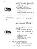
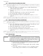
• If not, refer to Section 5-6.4.1.4, page 5-29, Function Code
L0 – Troll Enable and Control Head Lever Troll Range.
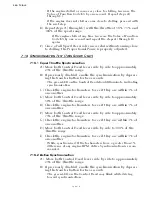
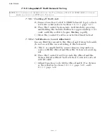
7-15.2.2 Troll Minimum Pressure Adjustment (Function Code L2)
A) Ensure that the Control Head lever is at the Neutral /
Idle position.
B) If the red LED is blinking rapidly, disable Troll by press-
ing the Transfer Button until the red LED becomes lit
solid.
C) Connect a Service Field Test Unit (P/N 14000) and
Ammeter to the Troll Command Signal output as
described in Section 2.3.2, page MM13927-16, of the
Service Field Test Unit Manual in Appendix B.
D) Move the Control Head lever to the Ahead detent.
E) Using a Shaft Tach, measure the RPM of the Shaft and
record.
F) Depress and hold (approximately 2 seconds) the Trans-
fer Button until the red LED starts blinking rapidly.
G) Measure the Shaft RPM and record.
H) Adjust the Value of Function Code
L2
until the Shaft
RPM is 30 to 50% of that measured in step E).
I) Enter the new Value into memory.
J) If twin screw application, repeat steps A) through H) on
the opposite side.
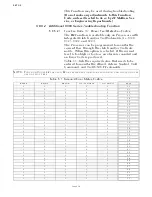
7-15.2.3 Troll Maximum Pressure Adjustment (Function Code L3)
A) Place one Control Head lever in the Ahead detent with
Troll enabled.
B) If twin screw, ensure that the opposite lever is at the
Neutral/ Idle position.
C) Scroll to Function Code
L3
and enter Setup Mode as
described in Section 5-2, page 5-5.
D) Increase or decrease the Value until the Shaft RPM is 70
to 80% of that measured in step E), page 7-8, of Section
7-15.2.2.
E) Enter the new Value into memory.
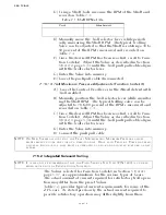
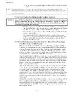
NOTE: D
O
N
OT
ATTEMPT
THE
FOLLOWING
ADJUSTMENTS
UNTIL
THE
G
EAR
OIL
TEMPERATURE
HAS
REACHED
A
MINIMUM
OF
140
DEGREES
F (60
DEGREES
C).
NOTE: T
HE
EFFECTS
OF
THE
FOLLOWING
ADJUSTMENTS
ARE
NOT
IMMEDIATE
. A
LLOW
ENOUGH
TIME
FOR
THE
S
HAFT
RPM
TO
STABILIZE
BETWEEN
ANY
CHANGES
TO
THE
L2
AND
L3 V
ALUES
.
NOTE: A
DJUST
THE
V
ALUE
OF
L2
BASED
ON
THE
DESIRED
VESSELS
WATER
SPEED
OR
SHAFT
RPM. D
O
NOT
BASE
THE
ADJUSTMENT
ON
THE
RESPONSE
TIME
(
HOW
QUICKLY
OR
SLOWLY
THE
SHAFT
BEGINS
TO
ROTATE
AFTER
SHIFTING
FROM
N
EUTRAL
TO
A
HEAD
OR
A
STERN
). T
HE
RESPONSE
TIME
MAY
BE
ADJUSTED
LATER
WITH
F
UNCTION
C
ODES
L5
AND
L6.
Содержание ClearCommand 9000 Series
Страница 1: ...ClearCommand 9000 Series Installation Operation and Troubleshooting Manual MM9000 I Rev C 2 5 08...
Страница 132: ......
Страница 133: ...APPENDIX A...
Страница 134: ......
Страница 139: ......
Страница 140: ...Page A 4...
Страница 143: ......
Страница 144: ...10...
Страница 148: ...Page A 18...
Страница 149: ...Page A 19 TEMPLATE...
Страница 150: ...Page A 20...
Страница 152: ...Page A 22...
Страница 154: ...Page A 24...
Страница 156: ...Page A 26...
Страница 157: ...Page A 27 Drawing 11488D 1 Twin Screw Single APS Connection Alternate Remote Switch...
Страница 158: ...Page A 28...
Страница 159: ...Page A 29 Drawing 11488D 2 Twin Screw Dual APS Connections...
Страница 160: ...Page A 30...
Страница 161: ...Page A 31 Drawing 11488D 3 APS Notes Page...
Страница 162: ...Page A 32...
Страница 164: ...Page A 34...
Страница 166: ...Page A 36...
Страница 170: ...Page A 40...
Страница 172: ...Page A 42...
Страница 176: ...Page A 46...
Страница 178: ...Page C 48 ZF Mathers LLC 12125 Harbour Reach Drive Suite B Mukilteo WA 98275...
Страница 179: ...APPENDIX B...
Страница 180: ......
Страница 234: ...Appendix B 6...
Страница 238: ...Appendix B 10...
Страница 242: ...Appendix B 14...
Страница 247: ...Service Field Test Unit Reference Manual MM13927 Rev E 4 07...
Страница 248: ......
Страница 250: ...Page ii Table of Contents...
Страница 264: ...SERVICE FIELD TEST UNIT MM13927 RvD 10 03 Page 3 2...
Страница 265: ...APPENDIX C...
Страница 266: ......
Страница 267: ...Appendix C 1 Drawing 12284A 1 ClearCommand Diagram all options...
Страница 268: ...Appendix C 2...
Страница 269: ...Appendix C 3 Drawing 12284A 2 ClearCommand Circuit Board Connections...
Страница 270: ...Appendix C 4...
Страница 271: ...Appendix C 5 Drawing 12284A 3 ClearCommand Drawing Notes Page...
Страница 272: ...Appendix C 6...

