


TROUBLESHOOTING
PageB1-1
B1 TROUBLESHOOTING GENERAL
The ClearCommand Control System consists of one Processor per
engine, typically mounted in the engine room, and one to five Control
Heads located at the vessel’s Remote Stations.
In the event that a malfunction occurs, review the appropriate Proces-
sor System Diagram and the descriptions in Section B1-1, page B1-1.
Become familiar with the various components, their functions and loca-
tion on the vessel.
Section B1-2, page B1-2, is a list of the main components that make up a
typical system, along with a brief description of their functions:
B1-1C
ONTROL
S
YSTEMS
E
XAMPLES
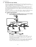
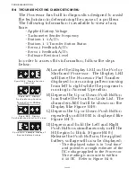
B1-1.1 9120 (Throttle Servo 2, Shift Solenoid) Processor and 9122 (Throttle
Servo 2, Shift Solenoid, Troll Solenoid) Processor
The
9120
Processor is designed to precisely control speed and
direction on vessels equipped with mechanical Throttle and
Solenoid Clutch Selectors.
The
9122
Processor is designed to precisely control speed, direc-
tion, and trolling valve on vessels equipped with mechanical
Throttle, Solenoid Clutch and Trolling Valve Selectors.
Figure B1-1: 9120 and 9122 Basic Single Screw, Two Station Diagram
SERIAL COMMUNICATION
10 AMP CIRCUIT BREAKERS
(BY OTHERS)
CLUTCH PRES.
START INTERLOCK
ALARM
START INTERLOCK
CLUTCH PRES.
ALARM
Содержание ClearCommand 9000 Series
Страница 1: ...ClearCommand 9000 Series Installation Operation and Troubleshooting Manual MM9000 I Rev C 2 5 08...
Страница 132: ......
Страница 133: ...APPENDIX A...
Страница 134: ......
Страница 139: ......
Страница 140: ...Page A 4...
Страница 143: ......
Страница 144: ...10...
Страница 148: ...Page A 18...
Страница 149: ...Page A 19 TEMPLATE...
Страница 150: ...Page A 20...
Страница 152: ...Page A 22...
Страница 154: ...Page A 24...
Страница 156: ...Page A 26...
Страница 157: ...Page A 27 Drawing 11488D 1 Twin Screw Single APS Connection Alternate Remote Switch...
Страница 158: ...Page A 28...
Страница 159: ...Page A 29 Drawing 11488D 2 Twin Screw Dual APS Connections...
Страница 160: ...Page A 30...
Страница 161: ...Page A 31 Drawing 11488D 3 APS Notes Page...
Страница 162: ...Page A 32...
Страница 164: ...Page A 34...
Страница 166: ...Page A 36...
Страница 170: ...Page A 40...
Страница 172: ...Page A 42...
Страница 176: ...Page A 46...
Страница 178: ...Page C 48 ZF Mathers LLC 12125 Harbour Reach Drive Suite B Mukilteo WA 98275...
Страница 179: ...APPENDIX B...
Страница 180: ......
Страница 234: ...Appendix B 6...
Страница 238: ...Appendix B 10...
Страница 242: ...Appendix B 14...
Страница 247: ...Service Field Test Unit Reference Manual MM13927 Rev E 4 07...
Страница 248: ......
Страница 250: ...Page ii Table of Contents...
Страница 264: ...SERVICE FIELD TEST UNIT MM13927 RvD 10 03 Page 3 2...
Страница 265: ...APPENDIX C...
Страница 266: ......
Страница 267: ...Appendix C 1 Drawing 12284A 1 ClearCommand Diagram all options...
Страница 268: ...Appendix C 2...
Страница 269: ...Appendix C 3 Drawing 12284A 2 ClearCommand Circuit Board Connections...
Страница 270: ...Appendix C 4...
Страница 271: ...Appendix C 5 Drawing 12284A 3 ClearCommand Drawing Notes Page...
Страница 272: ...Appendix C 6...


