


TROUBLESHOOTING
PageB5-1
B5 TROUBLESHOOTING AUDIBLE TONES
As mentioned previously, there are various tones emit-
ted from the Control Head if an error were to occur.
B5-1 B
ASIC
C
ONTROL
S
YSTEM
T
ONES
These basic tones are as follows:
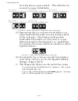
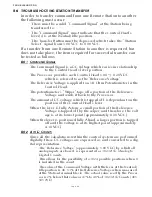
B5-1.1 Slow Repetitive Tone
The Slow Repetitive Tone, also referred to as the “Initialization
Tone” is the tone you hear at all Remote Stations when power is
initially applied to the control system. When this tone is heard,
you know for a fact that the following are true:
•
Power has just been applied to the system.
• The Software Program is running normally.
• The Processor is commanding the throttle to Idle.
• The Processor is commanding the clutch to Neutral.
This is a normal tone when power has first been applied to the
Processor and no Control Head has taken command. However,
the tone may also be an indication of a problem, if during normal
operation the engine’s throttle drops to Idle, followed by the
clutch to Neutral, the Control Head’s red LED goes out and a
slow repetitive tone is heard at all remote stations. This indicates
that the voltage at the Processor has momentarily dropped below
8 VDC
and then returned to a normal operational level. This
could be due to:
• Loose battery power cable connection.
• Under-charged or defective battery.
• Voltage drop due to current flow.
In order to pinpoint the exact cause of the low voltage at the Pro-
cessor, perform the following checks:
A) Check the Display on the Processor for Error Messages.
Error Message
57
may appear indicating Under Voltage.
One or more of Error Messages
43
through
54
may also be
displayed. This is due to the momentary loss of serial com-
munication between the two Processors. Take note that the
Under Voltage error is not only dependent on low voltage,
it is also dependent on the duration of the low voltage. The
possibility exists that an error message would not be dis-
played if the duration of the low voltage was short enough.
However, the other symptoms mentioned above still occur.
B) In either case, follow the procedure listed under
Diagnostic
Menu
(Section B4, page B4-1) until the Applied Battery
Voltage is displayed. Take note of the applied voltage.
C) Go to the battery or Main Distribution Panel which is feed-
ing power to the Processor. With a DC Voltmeter, measure
the voltage at this power source. The battery voltage
Figure B5-14: Slow Repetitive Tone
Содержание ClearCommand 9000 Series
Страница 1: ...ClearCommand 9000 Series Installation Operation and Troubleshooting Manual MM9000 I Rev C 2 5 08...
Страница 132: ......
Страница 133: ...APPENDIX A...
Страница 134: ......
Страница 139: ......
Страница 140: ...Page A 4...
Страница 143: ......
Страница 144: ...10...
Страница 148: ...Page A 18...
Страница 149: ...Page A 19 TEMPLATE...
Страница 150: ...Page A 20...
Страница 152: ...Page A 22...
Страница 154: ...Page A 24...
Страница 156: ...Page A 26...
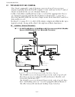
Страница 157: ...Page A 27 Drawing 11488D 1 Twin Screw Single APS Connection Alternate Remote Switch...
Страница 158: ...Page A 28...
Страница 159: ...Page A 29 Drawing 11488D 2 Twin Screw Dual APS Connections...
Страница 160: ...Page A 30...
Страница 161: ...Page A 31 Drawing 11488D 3 APS Notes Page...
Страница 162: ...Page A 32...
Страница 164: ...Page A 34...
Страница 166: ...Page A 36...
Страница 170: ...Page A 40...
Страница 172: ...Page A 42...
Страница 176: ...Page A 46...
Страница 178: ...Page C 48 ZF Mathers LLC 12125 Harbour Reach Drive Suite B Mukilteo WA 98275...
Страница 179: ...APPENDIX B...
Страница 180: ......
Страница 234: ...Appendix B 6...
Страница 238: ...Appendix B 10...
Страница 242: ...Appendix B 14...
Страница 247: ...Service Field Test Unit Reference Manual MM13927 Rev E 4 07...
Страница 248: ......
Страница 250: ...Page ii Table of Contents...
Страница 264: ...SERVICE FIELD TEST UNIT MM13927 RvD 10 03 Page 3 2...
Страница 265: ...APPENDIX C...
Страница 266: ......
Страница 267: ...Appendix C 1 Drawing 12284A 1 ClearCommand Diagram all options...
Страница 268: ...Appendix C 2...
Страница 269: ...Appendix C 3 Drawing 12284A 2 ClearCommand Circuit Board Connections...
Страница 270: ...Appendix C 4...
Страница 271: ...Appendix C 5 Drawing 12284A 3 ClearCommand Drawing Notes Page...
Страница 272: ...Appendix C 6...