


Page D-4
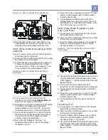
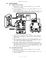
FIGURE D-8: THROTTLE CONNECTION (FREQUENCY HZ)
E) Turn power ‘On’ to the Processor and take
command at any Remote Station.
F) The appropriate Idle Frequency for the
application should be measured at this time.
G) Move the Control Head lever to the Full Throttle
position while depressing the Transfer Button
(Throttle Only Mode).
H) The appropriate Full Throttle Frequency for the
application should be measured at this time.
Procedure: Clutch Testing
Neutral Solenoid Testing
A) Ensure power is removed from both the Processor
and the Clutch Power Supply.
B) Disconnect the Clutch Harness from the number
3 Processor connector/pigtail.
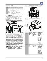
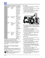
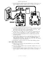
C) Insert the Break-out Box between the number 3
Processor connector/pigtail and the Clutch
Harness as shown in Figure D-9.
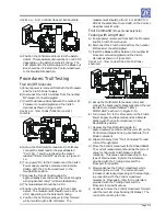
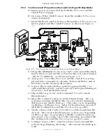
FIGURE D-9: CLUTCH CONNECTIONS NEUTRAL SOLENOID
D) Turn power ‘On’ to the Processor and take
command at any Remote Station with the Control
Head lever in the Neutral/Idle position.
E) The measurement on the Neutral Test Point
should be 12 or 24 VDC, depending on the
Solenoid’s rating and the LED adjacent to the
socket should be illuminated.
F) Move the Control Head lever to the Ahead Detent
position. The voltage should drop to 0 VDC in
CruiseCommand systems and remain at 12 or 24
VDC in ClearCommand systems. The adjacent
LED should go out in CruiseCommand systems
and stay on in ClearCommand systems.
Ahead Solenoid Testing
A) Ensure power is removed from both the Processor
and the Clutch Power Supply.
B) Disconnect the Clutch Harness from the number
3 Processor connector/pigtail.
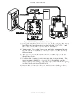
C) Insert the Break-out Box between the number 3
Processor connector/pigtail and the Clutch
Harness as shown in Figure D-10.
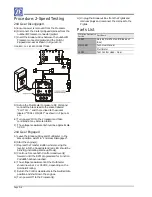
FIGURE D-10: CLUTCH CONNECTIONS AHEAD SOLENOID
D) Set up the Multimeter to measure DC Volts and
plug the black lead into the Break-out Box socket
labeled “CLUTCH -” and the red lead into the
socket labeled “AHEAD”.
E) Turn power ‘On’ to the Processor and take
command at any Remote Station with the lever in
the Neutral/Idle position.
F) The measurement should be 0 VDC and the
adjacent LED should not be lit.
G) Position the Control Head lever into the Ahead
detent. The measurement should be 12 or 24 VDC
depending on the Ahead Solenoid’s rating. The
LED adjacent to the Ahead plug on the Break-out
Box should be lit.
H) Return the Control Head lever to the Neutral/Idle
position.
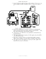
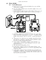
Astern Solenoid Testing
A) Ensure power is removed from both the Processor
and the Clutch Supply Power.
B) Disconnect the Clutch Harness from the number
3 Processor connector/pigtail.
C) Insert the Break-out Box between the number 3
Processor connector/pigtail and the Clutch
Harness as shown in Figure D-11.
D) Set up the Multimeter to measure DC Volts and
plug the black lead into the Break-out Box socket
labeled “CLUTCH -” and the red lead into the
socket labeled “ASTERN”.
E) Turn power ‘On’ to the Processor and take
command at any Remote Station with the Control
Head lever in the Neutral/Idle position.
F) The measurement should be 0 VDC and the
adjacent LED should not be lit.
Содержание ClearCommand 9000 Series
Страница 1: ...ClearCommand 9000 Series Installation Operation and Troubleshooting Manual MM9000 I Rev C 2 5 08...
Страница 132: ......
Страница 133: ...APPENDIX A...
Страница 134: ......
Страница 139: ......
Страница 140: ...Page A 4...
Страница 143: ......
Страница 144: ...10...
Страница 148: ...Page A 18...
Страница 149: ...Page A 19 TEMPLATE...
Страница 150: ...Page A 20...
Страница 152: ...Page A 22...
Страница 154: ...Page A 24...
Страница 156: ...Page A 26...
Страница 157: ...Page A 27 Drawing 11488D 1 Twin Screw Single APS Connection Alternate Remote Switch...
Страница 158: ...Page A 28...
Страница 159: ...Page A 29 Drawing 11488D 2 Twin Screw Dual APS Connections...
Страница 160: ...Page A 30...
Страница 161: ...Page A 31 Drawing 11488D 3 APS Notes Page...
Страница 162: ...Page A 32...
Страница 164: ...Page A 34...
Страница 166: ...Page A 36...
Страница 170: ...Page A 40...
Страница 172: ...Page A 42...
Страница 176: ...Page A 46...
Страница 178: ...Page C 48 ZF Mathers LLC 12125 Harbour Reach Drive Suite B Mukilteo WA 98275...
Страница 179: ...APPENDIX B...
Страница 180: ......
Страница 234: ...Appendix B 6...
Страница 238: ...Appendix B 10...
Страница 242: ...Appendix B 14...
Страница 247: ...Service Field Test Unit Reference Manual MM13927 Rev E 4 07...
Страница 248: ......
Страница 250: ...Page ii Table of Contents...
Страница 264: ...SERVICE FIELD TEST UNIT MM13927 RvD 10 03 Page 3 2...
Страница 265: ...APPENDIX C...
Страница 266: ......
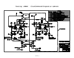
Страница 267: ...Appendix C 1 Drawing 12284A 1 ClearCommand Diagram all options...
Страница 268: ...Appendix C 2...
Страница 269: ...Appendix C 3 Drawing 12284A 2 ClearCommand Circuit Board Connections...
Страница 270: ...Appendix C 4...
Страница 271: ...Appendix C 5 Drawing 12284A 3 ClearCommand Drawing Notes Page...
Страница 272: ...Appendix C 6...