


SET UP
Page5-5
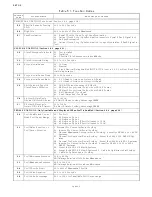
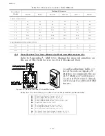
Function
Code
Function Name
Value Range or Options
THROTTLE FUNCTIONS continued (Section 5-6.2, page 5-14)
E5
Throttle Pause Following
Shift
00.0 to 05.0 Seconds
E6
High Idle
00.0 to 20.0% of Throttle Maximum
E7
Synchronization
00 – Equal Throttle (Open Loop) Synchronization
01 - Active (Closed Loop) Synchronization (reverts to Equal if Tach Signal lost)
02 - No Synchronization
03 - Active (Closed Loop) Synchronization (no synchronization if Tach Signal is
lost)
CLUTCH FUNCTIONS (Section 5-6.3, page 5-21)
C0
Clutch Pressure Interlock 00 – Not Installed
01 – Installed
02 – Throttle Clutch Pressure Interlock Mode
C1
Clutch Interlock Delay
00.5 to 10.0 Seconds
C2
Proportional Pause
00 – In-Gear
01 – Neutral
02 – Fixed Neutral Delay Enabled (NOTE: If C2 is set to 02, C3 will set Fixed Neu-
tral Delay duration.)
C3
Proportional Pause Time 00 to 99 Seconds
C4
Proportional Pause Ratio 00 – 2:1 Ahead to Astern vs. Astern to Ahead
01 – 1:1 Ahead to Astern vs. Astern to Ahead
C5
Shift Solenoid Type OR
Clutch Servo Direction
00 - All Shift Solenoids except ZF-Hurth
01 - ZF-Hurth Proportional Solenoids with 12V Power
02 - ZF-Hurth Proportional Solenoids with 24V Power
20 – Pull [Retracted] for Ahead
21 – Push [Extended] for Ahead
C6
ZF-Hurth Duty Cycle
Ahead OR Clutch Ahead
00 to 100%
ZF-Hurth Ahead Lockup Percentage PWM
C7
ZF-Hurth Duty Cycle
Astern OR Clutch Astern
00 to 100%
ZF-Hurth Astern Lockup Percentage PWM
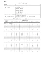
TROLL FUNCTIONS (Only Available and Displayed When Troll is Enabled) (Section 5-6.4, page 5-29)
L0
Troll Enable and Control
Head Troll Lever Range
00 – No Troll
01 – 20 Degrees- Type 1
02 – 35 Degrees- Type 2
03 – 45 Degrees- Type 3 (Throttle limited to 75%)
04 – 55 Degrees- Type 4 (Throttle limited to 10%))
L1
Troll Valve Function or
Troll Servo Direction
0 - Normal, No Current when at Lock-up
01 - Inverse, No Current when at Lock-up
02 - Normal, Maximum Current when at Lock-up. Preset for ZF220-550, 12VDC
Systems.
03 - Normal, No Current when at Lock-up. Preset for ZF220-550, 24VDC Sys-
tems.
04 - Normal, No Current when at Lock-up. Preset for ZF2000, 24 VDC Systems.
05 - Inverse, No Current when at Lock-up. Preset for ZF6000, 1900 or 2500,
24VDC Systems.
06 - Preset for 12VDC ZF Hurth Systems.
07 - Preset for 24VDC ZF Hurth Systems20 – Cable Fully Retracted at Lock-up.
21 – Cable Fully Extended at Lock-up.
L2
Troll Minimum Pressure 01.0 to 80.0%
Will always be at least 10% below Maximum.
L3
Troll Maximum Pressure 20.0 to 100.0%
Will always be at least 10% above Minimum.
L4
Troll Throttle Limit
00 to 20% of Maximum Throttle.
L5
Troll Pulse Duration
00.0 to 09.9 Seconds.
L6
Troll Pulse Percentage
00.1 to 100.0% of available Troll Servo range.
Table 5-1: Function Codes
Содержание ClearCommand 9000 Series
Страница 1: ...ClearCommand 9000 Series Installation Operation and Troubleshooting Manual MM9000 I Rev C 2 5 08...
Страница 132: ......
Страница 133: ...APPENDIX A...
Страница 134: ......
Страница 139: ......
Страница 140: ...Page A 4...
Страница 143: ......
Страница 144: ...10...
Страница 148: ...Page A 18...
Страница 149: ...Page A 19 TEMPLATE...
Страница 150: ...Page A 20...
Страница 152: ...Page A 22...
Страница 154: ...Page A 24...
Страница 156: ...Page A 26...
Страница 157: ...Page A 27 Drawing 11488D 1 Twin Screw Single APS Connection Alternate Remote Switch...
Страница 158: ...Page A 28...
Страница 159: ...Page A 29 Drawing 11488D 2 Twin Screw Dual APS Connections...
Страница 160: ...Page A 30...
Страница 161: ...Page A 31 Drawing 11488D 3 APS Notes Page...
Страница 162: ...Page A 32...
Страница 164: ...Page A 34...
Страница 166: ...Page A 36...
Страница 170: ...Page A 40...
Страница 172: ...Page A 42...
Страница 176: ...Page A 46...
Страница 178: ...Page C 48 ZF Mathers LLC 12125 Harbour Reach Drive Suite B Mukilteo WA 98275...
Страница 179: ...APPENDIX B...
Страница 180: ......
Страница 234: ...Appendix B 6...
Страница 238: ...Appendix B 10...
Страница 242: ...Appendix B 14...
Страница 247: ...Service Field Test Unit Reference Manual MM13927 Rev E 4 07...
Страница 248: ......
Страница 250: ...Page ii Table of Contents...
Страница 264: ...SERVICE FIELD TEST UNIT MM13927 RvD 10 03 Page 3 2...
Страница 265: ...APPENDIX C...
Страница 266: ......
Страница 267: ...Appendix C 1 Drawing 12284A 1 ClearCommand Diagram all options...
Страница 268: ...Appendix C 2...
Страница 269: ...Appendix C 3 Drawing 12284A 2 ClearCommand Circuit Board Connections...
Страница 270: ...Appendix C 4...
Страница 271: ...Appendix C 5 Drawing 12284A 3 ClearCommand Drawing Notes Page...
Страница 272: ...Appendix C 6...