


OPERATION
Page 2-17
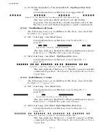
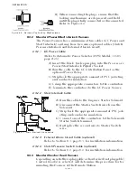
2-13.7 9001 Trolling Actuator Tones (Servo 3)
The following Tones are in addition to the Basic Tones listed in
Section 5-6.4.1, page 5-29.
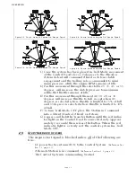
2-13.7.1 One Long, Four Short Tones
Detail information on this tone is in the Manual supplied
with the 9001 Trolling Actuator.
This tone indicates that there is a feedback error in the
Trolling Actuator.
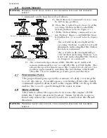
2-13.7.2 One Long, Four Short - High Repetitive Rate Tone
Detail information on this tone is in the Manual supplied
with the 9001 Trolling Actuator.
This tone indicates that Trolling Actuator Servo cannot
reach the commanded position.
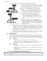
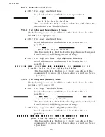
2-13.8 Troll Integrated Solenoid Tones
2-13.8.3 Three Second Steady Tone
This tone indicates that the Troll Solenoid is OPEN or
shorted. Refer to the Error Code displayed for further
information.
2-14 P
USH
B
UTTON
S
ET
U
P
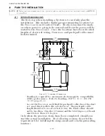
There are four push buttons mounted to the Processor’s circuit
board. These push buttons allow the installer/technician access to
all of the Functions required for programming and troubleshoot-
ing the Processor.
A full description of their usage is provided in Section 5-1.2,
page 5-2.
2-15 V
ISUAL
S
YSTEM
D
IAGNOSTICS
, S
ET
U
P
A
ND
S
TATUS
I
NDICATION
There are four, seven segment LED’s (hereafter referred to as the
Display LED) mounted to the Processor’s circuit board. The Dis-
play LED is visible through a transparent window in the Proces-
sor’s cover. The information displayed on the Display LED is used
in conjunction with the push buttons to program the Processor.
The Display LED also displays Error Codes in the event that an
anomaly is detected.
For a full description of the Display LED, its capability and usage,
refer to Section 5-1.1, page 5-2.
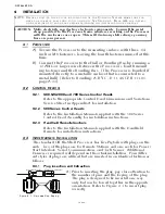
Figure 2-29: One Long - Four Short Tones
Figure 2-30: One Long, Four Short - High Repetitive Rate Tone
Figure 2-31: Three Second Steady Tone
Содержание ClearCommand 9000 Series
Страница 1: ...ClearCommand 9000 Series Installation Operation and Troubleshooting Manual MM9000 I Rev C 2 5 08...
Страница 132: ......
Страница 133: ...APPENDIX A...
Страница 134: ......
Страница 139: ......
Страница 140: ...Page A 4...
Страница 143: ......
Страница 144: ...10...
Страница 148: ...Page A 18...
Страница 149: ...Page A 19 TEMPLATE...
Страница 150: ...Page A 20...
Страница 152: ...Page A 22...
Страница 154: ...Page A 24...
Страница 156: ...Page A 26...
Страница 157: ...Page A 27 Drawing 11488D 1 Twin Screw Single APS Connection Alternate Remote Switch...
Страница 158: ...Page A 28...
Страница 159: ...Page A 29 Drawing 11488D 2 Twin Screw Dual APS Connections...
Страница 160: ...Page A 30...
Страница 161: ...Page A 31 Drawing 11488D 3 APS Notes Page...
Страница 162: ...Page A 32...
Страница 164: ...Page A 34...
Страница 166: ...Page A 36...
Страница 170: ...Page A 40...
Страница 172: ...Page A 42...
Страница 176: ...Page A 46...
Страница 178: ...Page C 48 ZF Mathers LLC 12125 Harbour Reach Drive Suite B Mukilteo WA 98275...
Страница 179: ...APPENDIX B...
Страница 180: ......
Страница 234: ...Appendix B 6...
Страница 238: ...Appendix B 10...
Страница 242: ...Appendix B 14...
Страница 247: ...Service Field Test Unit Reference Manual MM13927 Rev E 4 07...
Страница 248: ......
Страница 250: ...Page ii Table of Contents...
Страница 264: ...SERVICE FIELD TEST UNIT MM13927 RvD 10 03 Page 3 2...
Страница 265: ...APPENDIX C...
Страница 266: ......
Страница 267: ...Appendix C 1 Drawing 12284A 1 ClearCommand Diagram all options...
Страница 268: ...Appendix C 2...
Страница 269: ...Appendix C 3 Drawing 12284A 2 ClearCommand Circuit Board Connections...
Страница 270: ...Appendix C 4...
Страница 271: ...Appendix C 5 Drawing 12284A 3 ClearCommand Drawing Notes Page...
Страница 272: ...Appendix C 6...