


INSTALLATION
Page4-3
•
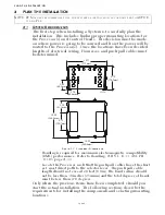
The first installation procedure (Section 4-3.3.1) below is written
for the pluggable Control Head.
• If a hard-wired Control Head(s) is selected, follow the informa-
tion provided in the second procedure (Section 4-3.3.2, page 4-3)
:
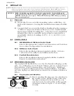
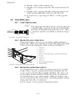
4-3.3.1 Control Head Harness with Two Connectors
A) At the Port Processor, insert the grey, eight pin plug into
the Station 1 pigtail plug.
B) Run the cable to the Control Head located at Station 1.
C) Insert the grey, eight pin plug into the Control Head’s
Port pigtail plug.
D) Ensure that the cable has a strain relief close to the Con-
trol Head to relieve the strain on the connections.
E) Repeat Steps A) thru D) for the Starboard Processor.
F) Repeat Steps A) thru E) with Station 2.
G) When Stations 3, 4 and 5 are to be installed, they each
require the removal of the watertight seal located on the
Processor enclosure in the Station cable entry holes.
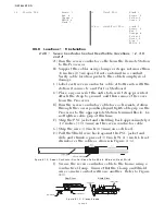
4-3.3.2 Control Head Harness with One Plug
A) At the Port Processor, insert the grey, eight pin plug into
the Station 1 pigtail plug.
B) Run the cable to the Port side of the Control Head
located at Station 1.
C) Connect the conductors to the Control Head as
described in the appropriate Control Head Dimensions
and Variations Service Sheet in Appendix A.
D) Provide a strain relief in close proximity to the Control
Head’s terminal block.
E) Repeat Steps A) thru D) for the Starboard Processor.
F) Repeat steps A) thru E) with Station 2.
G) When Stations 3, 4 and 5 are to be installed, they each
require the removal of the watertight seal located on the
Processor enclosure in the Station cable entry holes.
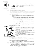
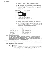
4-3.4 Serial Communication Harness (Twin Screw only)
A) At the Processors, remove the watertight seals from the Serial
pigtail plugs.
B) At the Port Processor, insert the grey, six pin plug into the
Serial pigtail plug.
C) Run the cable to the Starboard Processor.
D) At the Starboard Processor, insert the grey, six pin plug into
the Serial pigtail plug.
NOTE: F
OR
T
WIN
S
CREW
, D
UAL
L
EVER
C
ONTROL
H
EADS
MUST
BE
CONNECTED
TO
THE
SAME
NUM
-
BERED
S
TATION
ON
BOTH
P
ROCESSORS
.
Содержание ClearCommand 9000 Series
Страница 1: ...ClearCommand 9000 Series Installation Operation and Troubleshooting Manual MM9000 I Rev C 2 5 08...
Страница 132: ......
Страница 133: ...APPENDIX A...
Страница 134: ......
Страница 139: ......
Страница 140: ...Page A 4...
Страница 143: ......
Страница 144: ...10...
Страница 148: ...Page A 18...
Страница 149: ...Page A 19 TEMPLATE...
Страница 150: ...Page A 20...
Страница 152: ...Page A 22...
Страница 154: ...Page A 24...
Страница 156: ...Page A 26...
Страница 157: ...Page A 27 Drawing 11488D 1 Twin Screw Single APS Connection Alternate Remote Switch...
Страница 158: ...Page A 28...
Страница 159: ...Page A 29 Drawing 11488D 2 Twin Screw Dual APS Connections...
Страница 160: ...Page A 30...
Страница 161: ...Page A 31 Drawing 11488D 3 APS Notes Page...
Страница 162: ...Page A 32...
Страница 164: ...Page A 34...
Страница 166: ...Page A 36...
Страница 170: ...Page A 40...
Страница 172: ...Page A 42...
Страница 176: ...Page A 46...
Страница 178: ...Page C 48 ZF Mathers LLC 12125 Harbour Reach Drive Suite B Mukilteo WA 98275...
Страница 179: ...APPENDIX B...
Страница 180: ......
Страница 234: ...Appendix B 6...
Страница 238: ...Appendix B 10...
Страница 242: ...Appendix B 14...
Страница 247: ...Service Field Test Unit Reference Manual MM13927 Rev E 4 07...
Страница 248: ......
Страница 250: ...Page ii Table of Contents...
Страница 264: ...SERVICE FIELD TEST UNIT MM13927 RvD 10 03 Page 3 2...
Страница 265: ...APPENDIX C...
Страница 266: ......
Страница 267: ...Appendix C 1 Drawing 12284A 1 ClearCommand Diagram all options...
Страница 268: ...Appendix C 2...
Страница 269: ...Appendix C 3 Drawing 12284A 2 ClearCommand Circuit Board Connections...
Страница 270: ...Appendix C 4...
Страница 271: ...Appendix C 5 Drawing 12284A 3 ClearCommand Drawing Notes Page...
Страница 272: ...Appendix C 6...