


TROUBLESHOOTING
PageB5-3
A) Check the Processor’s Display for error messages. Most
likely, one of error messages
13
thru
32
will be shown. The
exact number shown depends on which remote station is
experiencing the problem and whether the command sig-
nal was too high or too low.
B) Enter the Diagnostic Menu as outlined in Section B4,
page B4-1.
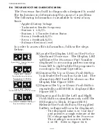
C) Depress the Up or Down (Scroll) Push Button until the
appropriate Remote Station is displayed.
•
The Remote Station are identified by the position of the deci-
mal points.
• Station 1 has no decimal point after the first digit to the far
right. The remaining three digits all have decimal points.
• If the digit to the far left had no decimal point following it, but
the remaining three do, this would represent Station 4.
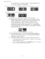
D) The examples in Figure B5-16: are shown with no Control
Heads connected to any Remote Stations. When a Control
Head is connected, the appropriate A/D (Analog/Digital)
value for the present position of the Control Head’s lever
will be shown, as in the examples below:
E) An A/D value of 910 or greater will generate an Error Code.
The code will be
13
to
22
(Control Head # Faulted High),
depending on which Station has the high Command Signal.
• If the A/D value is greater than 910, but less than 990, one of
the following may be the cause:
1. The Control Head’s potentiometer is out of calibration.
2. The potentiometer is defective.
In either case, it is recommended that the Control
Head is replaced.
S
TATION
1
S
TATION
4
S
TATION
2
S
TATION
5
S
TATION
3
Figure B5-16: Display Examples of Remote Stations
S
TATION
1
(N
EUTRAL
C
OMMANDED
)
S
TATION
4
(N
O
C
ONTROL
H
EAD
C
ONNECTED
)
S
TATION
2
(F
ULL
A
HEAD
C
OMMANDED
)
S
TATION
5
(N
EUTRAL
C
OMMANDED
)
S
TATION
3
(F
ULL
A
STERN
C
OMMANDED
)
Figure B5-17: Display Examples of Remote Stations A/D Value
Содержание ClearCommand 9000 Series
Страница 1: ...ClearCommand 9000 Series Installation Operation and Troubleshooting Manual MM9000 I Rev C 2 5 08...
Страница 132: ......
Страница 133: ...APPENDIX A...
Страница 134: ......
Страница 139: ......
Страница 140: ...Page A 4...
Страница 143: ......
Страница 144: ...10...
Страница 148: ...Page A 18...
Страница 149: ...Page A 19 TEMPLATE...
Страница 150: ...Page A 20...
Страница 152: ...Page A 22...
Страница 154: ...Page A 24...
Страница 156: ...Page A 26...
Страница 157: ...Page A 27 Drawing 11488D 1 Twin Screw Single APS Connection Alternate Remote Switch...
Страница 158: ...Page A 28...
Страница 159: ...Page A 29 Drawing 11488D 2 Twin Screw Dual APS Connections...
Страница 160: ...Page A 30...
Страница 161: ...Page A 31 Drawing 11488D 3 APS Notes Page...
Страница 162: ...Page A 32...
Страница 164: ...Page A 34...
Страница 166: ...Page A 36...
Страница 170: ...Page A 40...
Страница 172: ...Page A 42...
Страница 176: ...Page A 46...
Страница 178: ...Page C 48 ZF Mathers LLC 12125 Harbour Reach Drive Suite B Mukilteo WA 98275...
Страница 179: ...APPENDIX B...
Страница 180: ......
Страница 234: ...Appendix B 6...
Страница 238: ...Appendix B 10...
Страница 242: ...Appendix B 14...
Страница 247: ...Service Field Test Unit Reference Manual MM13927 Rev E 4 07...
Страница 248: ......
Страница 250: ...Page ii Table of Contents...
Страница 264: ...SERVICE FIELD TEST UNIT MM13927 RvD 10 03 Page 3 2...
Страница 265: ...APPENDIX C...
Страница 266: ......
Страница 267: ...Appendix C 1 Drawing 12284A 1 ClearCommand Diagram all options...
Страница 268: ...Appendix C 2...
Страница 269: ...Appendix C 3 Drawing 12284A 2 ClearCommand Circuit Board Connections...
Страница 270: ...Appendix C 4...
Страница 271: ...Appendix C 5 Drawing 12284A 3 ClearCommand Drawing Notes Page...
Страница 272: ...Appendix C 6...