


SET UP
Page5-24
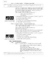
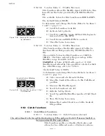
5-6.5.1.6 Function Code L5 – Troll Pulse Duration
This Function determines the length of time that the
Value selected in Function Code
L6
is applied.
The available Values for this Function are
00.0
to
09.9
seconds.
The default Value is
00.6
seconds.
To determine, and if required, change the Value
(Refer to Sections 5-2 and 5-3, page 5-5):
A) With Troll selected, place the Control Head
lever into the Ahead detent.
• If the vessel lunges forward or the shaft takes
too long to start rotating, continue with the next
step.
B) Scroll to Function Code
L5
.
C) Activate Set Up Mode.
D) Scroll Up or Down to the desired Value.
E) Store the Value to memory.
5-6.5.2 Troll Servo Functions
This section along with Section 5-6.4.1, page 5-29, Basic
Troll Command Functions allows the adjustment of Troll
Servo related items:
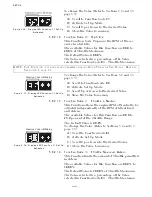
5-6.5.2.1 Function Code L1 – Troll Servo Direction
This Function Code determines whether the Troll
Push-Pull cable is fully extended or retracted when at
Lock-up.
The available Values are:
20
Lock-up – Push-Pull cable fully retracted. (Default
Value)
21
Lock-up – Push-Pull cable fully extended.
To determine, and if required, change the Value
(Refer to Sections 5-2 and 5-3, page 5-5):
NOTE: A
LL
T
ROLL
F
UNCTIONS
OTHER
THAN
L0
WILL
NOT
BE
DISPLAYED
ON
THE
P
ROCESSOR
D
ISPLAY
LED
IF
F
UNCTION
L0
IS
SET
TO
00
. T
O
UTILIZED
T
ROLL
AND
DISPLAY
THE
REST
OF
THE
T
ROLL
F
UNCTIONS
,
A
VALUE
OTHER
THAN
00
NEEDS
TO
BE
ENTERED
FOR
F
UNCTION
L0
.
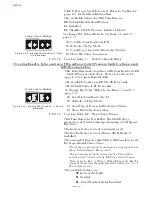
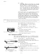
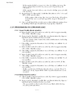
Figure 5-50: Display LED
Function L1 Set Up Activated
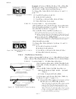
A) Move the Troll Selector Lever to the Lock-up
(Full Pressure) position.
B) Check to see if the Push-Pull cable’s ball joint
are in close proximity to one another.
• If so, no adjustments of Function Code
L1
Troll
Servo Direction are required.
• If they are not, continue with the next step.
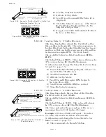
C) Scroll to Function Code
L1
.
D) Activate Set Up Mode.
E) Scroll Up or Down to Value
20
or
21
.
F) Store the Value to memory
Содержание ClearCommand 9000 Series
Страница 1: ...ClearCommand 9000 Series Installation Operation and Troubleshooting Manual MM9000 I Rev C 2 5 08...
Страница 132: ......
Страница 133: ...APPENDIX A...
Страница 134: ......
Страница 139: ......
Страница 140: ...Page A 4...
Страница 143: ......
Страница 144: ...10...
Страница 148: ...Page A 18...
Страница 149: ...Page A 19 TEMPLATE...
Страница 150: ...Page A 20...
Страница 152: ...Page A 22...
Страница 154: ...Page A 24...
Страница 156: ...Page A 26...
Страница 157: ...Page A 27 Drawing 11488D 1 Twin Screw Single APS Connection Alternate Remote Switch...
Страница 158: ...Page A 28...
Страница 159: ...Page A 29 Drawing 11488D 2 Twin Screw Dual APS Connections...
Страница 160: ...Page A 30...
Страница 161: ...Page A 31 Drawing 11488D 3 APS Notes Page...
Страница 162: ...Page A 32...
Страница 164: ...Page A 34...
Страница 166: ...Page A 36...
Страница 170: ...Page A 40...
Страница 172: ...Page A 42...
Страница 176: ...Page A 46...
Страница 178: ...Page C 48 ZF Mathers LLC 12125 Harbour Reach Drive Suite B Mukilteo WA 98275...
Страница 179: ...APPENDIX B...
Страница 180: ......
Страница 234: ...Appendix B 6...
Страница 238: ...Appendix B 10...
Страница 242: ...Appendix B 14...
Страница 247: ...Service Field Test Unit Reference Manual MM13927 Rev E 4 07...
Страница 248: ......
Страница 250: ...Page ii Table of Contents...
Страница 264: ...SERVICE FIELD TEST UNIT MM13927 RvD 10 03 Page 3 2...
Страница 265: ...APPENDIX C...
Страница 266: ......
Страница 267: ...Appendix C 1 Drawing 12284A 1 ClearCommand Diagram all options...
Страница 268: ...Appendix C 2...
Страница 269: ...Appendix C 3 Drawing 12284A 2 ClearCommand Circuit Board Connections...
Страница 270: ...Appendix C 4...
Страница 271: ...Appendix C 5 Drawing 12284A 3 ClearCommand Drawing Notes Page...
Страница 272: ...Appendix C 6...