


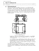


PLAN THE INSTALLATION
Page3-5
2
TWO
-
CONDUCTOR
CABLES
FOR
T
ROLL
ON/OFF
AND
T
ROLL
P
ROPORTIONAL
S
OLENOIDS
.
• The Power for the clutches and troll are supplied by the Pro-
cessor’s power source.
• All of the cables in the Harness are the same length. There-
fore, order a length that will reach all of the previously men-
tioned items, if required.
3-1.5 Standard Electric Cables
(Refer to the PARTS LIST, page A-1)
The following lists the various equivalent electric cables for the
basic connections to the Standard Processor:
3-1.5.1 Control Head Electric Cable
If the Control Head is hard-wired (no plugs) the electric
cable must meet the following specifications or may be
ordered from ZF Mathers:
• Seven-conductor with shield, twisted.
• Color Code – black, brown, red, orange, green, blue, and
violet.
• 18 AWG (nearest metric equivalent - #1).
• 300V, 105 degrees C, UL VW1, stranded tinned copper
wire.
• Maximum outside diameter: 0.390 inch (9,9mm)
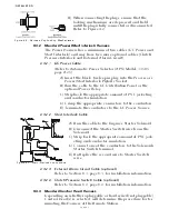
3-1.5.2 Power, Start Interlock, Clutch Pressure, Alarm Electric Cable
3-1.5.2.1 Power Electric Cable Requirements
If Power is hard-wired, (no plugs) the electric cable must meet
the following specifications or may be ordered from ZF
Mathers:
• Two-conductor, black and red with violet stripe,
twisted.
• 14 AWG (#2,5 metric) or 12 AWG (#4 metric) may
be used to crimp directly to the Processor termi-
nals. Refer to S-214 Rev.E 5/03 Automatic Power
Selector (APS) Model: 13505 in Appendix A for
cable length and additional wire size requirements.
• 300V, 105 degrees C, UL VW1, stranded tinned
copper wire.
• Maximum outside diameter: 0.390 inch (9,9mm).
3-1.5.2.2 Start Interlock Electric Cable Requirements
If Start Interlock is hard-wired (no plugs) the electric cable
must meet the following specifications or may be ordered
from ZF Mathers:
• Two-conductor, both yellow with red stripe,
twisted.
• 16 AWG (#1,5 metric).
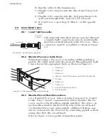
NOTE: S
OME
TRANSMISSIONS
ONLY
UTILIZE
ONE
SOLENOID
FOR
TROLL
,
THEREFORE
,
THE
HARNESS
WOULD
CONSIST
OF
ONLY
THREE
CABLES
.
Содержание ClearCommand 9000 Series
Страница 1: ...ClearCommand 9000 Series Installation Operation and Troubleshooting Manual MM9000 I Rev C 2 5 08...
Страница 132: ......
Страница 133: ...APPENDIX A...
Страница 134: ......
Страница 139: ......
Страница 140: ...Page A 4...
Страница 143: ......
Страница 144: ...10...
Страница 148: ...Page A 18...
Страница 149: ...Page A 19 TEMPLATE...
Страница 150: ...Page A 20...
Страница 152: ...Page A 22...
Страница 154: ...Page A 24...
Страница 156: ...Page A 26...
Страница 157: ...Page A 27 Drawing 11488D 1 Twin Screw Single APS Connection Alternate Remote Switch...
Страница 158: ...Page A 28...
Страница 159: ...Page A 29 Drawing 11488D 2 Twin Screw Dual APS Connections...
Страница 160: ...Page A 30...
Страница 161: ...Page A 31 Drawing 11488D 3 APS Notes Page...
Страница 162: ...Page A 32...
Страница 164: ...Page A 34...
Страница 166: ...Page A 36...
Страница 170: ...Page A 40...
Страница 172: ...Page A 42...
Страница 176: ...Page A 46...
Страница 178: ...Page C 48 ZF Mathers LLC 12125 Harbour Reach Drive Suite B Mukilteo WA 98275...
Страница 179: ...APPENDIX B...
Страница 180: ......
Страница 234: ...Appendix B 6...
Страница 238: ...Appendix B 10...
Страница 242: ...Appendix B 14...
Страница 247: ...Service Field Test Unit Reference Manual MM13927 Rev E 4 07...
Страница 248: ......
Страница 250: ...Page ii Table of Contents...
Страница 264: ...SERVICE FIELD TEST UNIT MM13927 RvD 10 03 Page 3 2...
Страница 265: ...APPENDIX C...
Страница 266: ......
Страница 267: ...Appendix C 1 Drawing 12284A 1 ClearCommand Diagram all options...
Страница 268: ...Appendix C 2...
Страница 269: ...Appendix C 3 Drawing 12284A 2 ClearCommand Circuit Board Connections...
Страница 270: ...Appendix C 4...
Страница 271: ...Appendix C 5 Drawing 12284A 3 ClearCommand Drawing Notes Page...
Страница 272: ...Appendix C 6...