


TROUBLESHOOTING
PageB1-4
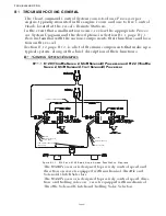
B1-2 T
YPICAL
S
YSTEM
M
AIN
C
OMPONENTS
B1-2.1 Control Head
The primary function of the Control Head is to send out a vari-
able DC voltage to the Processor. This DC voltage is representa-
tive of the Control Head’s present lever position. In addition to
the primary function, the Control Head also has audible (Sound
Transducer) and visual (LED) status indications, along with a
Transfer Button for taking command and performing other sys-
tem functions.
B1-2.2 Processor
The Processor receives the variable DC voltage from the Control
Head(s) and converts these inputs to the appropriate electronic
or electric outputs at the correct time and sequence to the Gover-
nor and Gear Box. The information regarding throttle type,
throttle/ clutch sequencing, etc., are all stored on memory within
the Processor.
B1-2.3 Power Source
All electronic equipment must have power in order to operate.
Ensuring a properly charged reliable power source is available is
crucial. The Processor requires a 12 or 24 VDC power system.
The minimum voltage at which the Processor will continue to
operate is 8.00 VDC. The maximum allowable voltage is 30 VDC.
Exceeding these limits will not damage the Processor, but will
render it unusable temporarily. The power supply must be capa-
ble of delivering 10 amperes to each Processor on a continual
basis and current surges up to 20 amperes.
All cable calculations should be based on a 10 ampere draw with
no more than 10% voltage drop.
B1-2.4 Electrical Cables and Harnesses
The function of the Electrical Cables and Harnesses are to move
electrical information from one point to another. The ZF
Mathers’ System has electrical cables and/or pluggable Har-
nesses. These Harnesses may have plugs on one end or both,
depending on its purpose.
There are Harnesses available for Control Head Interface, DC
Power, Start Interlock, Clutch Oil Pressure Interlock and Exter-
nal System Status Indication Circuit. Not all of the above har-
nesses may be used. In addition, the application may require
Harnesses for one or more of the following: Engine Interface,
Shift Interface, Troll Interface, Serial Communication and
Tachometer Sensor Signal.
B1-2.5 Push-Pull Cables
The primary function of a Push-Pull cable is to allow a physical
movement on one end to be felt at the opposite end with a mini-
mum of back-lash. The Push-Pull cables are mechanically con-
nected to the Processor’s cross-bars on one end and the governor
and/or transmission selector levers on the end. The Processor
Содержание ClearCommand 9000 Series
Страница 1: ...ClearCommand 9000 Series Installation Operation and Troubleshooting Manual MM9000 I Rev C 2 5 08...
Страница 132: ......
Страница 133: ...APPENDIX A...
Страница 134: ......
Страница 139: ......
Страница 140: ...Page A 4...
Страница 143: ......
Страница 144: ...10...
Страница 148: ...Page A 18...
Страница 149: ...Page A 19 TEMPLATE...
Страница 150: ...Page A 20...
Страница 152: ...Page A 22...
Страница 154: ...Page A 24...
Страница 156: ...Page A 26...
Страница 157: ...Page A 27 Drawing 11488D 1 Twin Screw Single APS Connection Alternate Remote Switch...
Страница 158: ...Page A 28...
Страница 159: ...Page A 29 Drawing 11488D 2 Twin Screw Dual APS Connections...
Страница 160: ...Page A 30...
Страница 161: ...Page A 31 Drawing 11488D 3 APS Notes Page...
Страница 162: ...Page A 32...
Страница 164: ...Page A 34...
Страница 166: ...Page A 36...
Страница 170: ...Page A 40...
Страница 172: ...Page A 42...
Страница 176: ...Page A 46...
Страница 178: ...Page C 48 ZF Mathers LLC 12125 Harbour Reach Drive Suite B Mukilteo WA 98275...
Страница 179: ...APPENDIX B...
Страница 180: ......
Страница 234: ...Appendix B 6...
Страница 238: ...Appendix B 10...
Страница 242: ...Appendix B 14...
Страница 247: ...Service Field Test Unit Reference Manual MM13927 Rev E 4 07...
Страница 248: ......
Страница 250: ...Page ii Table of Contents...
Страница 264: ...SERVICE FIELD TEST UNIT MM13927 RvD 10 03 Page 3 2...
Страница 265: ...APPENDIX C...
Страница 266: ......
Страница 267: ...Appendix C 1 Drawing 12284A 1 ClearCommand Diagram all options...
Страница 268: ...Appendix C 2...
Страница 269: ...Appendix C 3 Drawing 12284A 2 ClearCommand Circuit Board Connections...
Страница 270: ...Appendix C 4...
Страница 271: ...Appendix C 5 Drawing 12284A 3 ClearCommand Drawing Notes Page...
Страница 272: ...Appendix C 6...


