


TROUBLESHOOTING
PageB3-2
B3-3 C
OMPONENT
C
ONDITION
B3-3.1 Control Heads
Inspect for any signs of corrosion due to water incursion. If
hard-wired, ensure that all the fork connectors are properly
secured to the terminal. Verify all wires are fully crimped and
do not pull loose.
B3-3.2 Processors
Inspect the Processor for any signs of physical damage.
B3-4 I
NTERCONNECTING
W
IRING
AND
H
ARNESSES
A) Inspect the wire terminations for loose connections,
corrosion or wire strands.
B) Inspect the Harness’s pins and sockets for bent pins,
torn boots or any signs of corrosion.
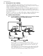
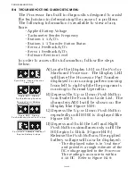
The first step in troubleshooting a problem with the Propulsion
System is to determine if the problem is with the Control System or
something external to the System. In all cases a Control System
malfunction will alert the operator of the potential problem. This
is accomplished through the audible tone emitted at all Remote Sta-
tions. When an audible tone is emitted, it will be accompanied by
an Error Message at the Processor. Also, in many cases, the Con-
trol System will alert the operator to a problem external to the Con-
trol System.
The following are examples of components both internal and exter-
nal to the Control System which could be a source of trouble:
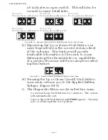
The following pages should give you a good guideline for making
this determination. There is no need to troubleshoot the system to
any point further than one of the main components listed above. If
the fault is found to be with a Control System component, that
component is simply replaced. If the fault is found to be with one
of the external components, replace or repair the defective compo-
nent or contact a qualified mechanic.
Table B3-2: Examples of Components (Internal/External)
Internal
External
1) Processor
2) Control Head
3) Interconnecting Wiring (Harnesses)
4) Push-Pull Cable
1) DC Power Source
2) Engine
3) Transmission
4) Push-Pull Cable
Содержание ClearCommand 9000 Series
Страница 1: ...ClearCommand 9000 Series Installation Operation and Troubleshooting Manual MM9000 I Rev C 2 5 08...
Страница 132: ......
Страница 133: ...APPENDIX A...
Страница 134: ......
Страница 139: ......
Страница 140: ...Page A 4...
Страница 143: ......
Страница 144: ...10...
Страница 148: ...Page A 18...
Страница 149: ...Page A 19 TEMPLATE...
Страница 150: ...Page A 20...
Страница 152: ...Page A 22...
Страница 154: ...Page A 24...
Страница 156: ...Page A 26...
Страница 157: ...Page A 27 Drawing 11488D 1 Twin Screw Single APS Connection Alternate Remote Switch...
Страница 158: ...Page A 28...
Страница 159: ...Page A 29 Drawing 11488D 2 Twin Screw Dual APS Connections...
Страница 160: ...Page A 30...
Страница 161: ...Page A 31 Drawing 11488D 3 APS Notes Page...
Страница 162: ...Page A 32...
Страница 164: ...Page A 34...
Страница 166: ...Page A 36...
Страница 170: ...Page A 40...
Страница 172: ...Page A 42...
Страница 176: ...Page A 46...
Страница 178: ...Page C 48 ZF Mathers LLC 12125 Harbour Reach Drive Suite B Mukilteo WA 98275...
Страница 179: ...APPENDIX B...
Страница 180: ......
Страница 234: ...Appendix B 6...
Страница 238: ...Appendix B 10...
Страница 242: ...Appendix B 14...
Страница 247: ...Service Field Test Unit Reference Manual MM13927 Rev E 4 07...
Страница 248: ......
Страница 250: ...Page ii Table of Contents...
Страница 264: ...SERVICE FIELD TEST UNIT MM13927 RvD 10 03 Page 3 2...
Страница 265: ...APPENDIX C...
Страница 266: ......
Страница 267: ...Appendix C 1 Drawing 12284A 1 ClearCommand Diagram all options...
Страница 268: ...Appendix C 2...
Страница 269: ...Appendix C 3 Drawing 12284A 2 ClearCommand Circuit Board Connections...
Страница 270: ...Appendix C 4...
Страница 271: ...Appendix C 5 Drawing 12284A 3 ClearCommand Drawing Notes Page...
Страница 272: ...Appendix C 6...