


INSTALLATION
Page4-9
4-4.6 Locations 1 - 9 Installation
4-4.6.1 Seven-Conductor Control Head Cable (Locations 1, 2, 3, 6,
and 7)
A) Run the seven-conductor cable from the Remote Station
to the Processor.
B) Support the cables using clamps or straps not more than
18 inches (0,5m) apart if not contained in a conduit.
Verify cable location protects the cable from physical
damage.
C) Label each seven-conductor cable at both ends with the
station it connects, and Port or Starboard.
D) Place on your wrist the anti-static wrist strap provided,
attach the strap to ground, and then remove the cover
from the Processor.
E) Run the seven-conductor cable for each remote station
through the corresponding liquid tight cable grip on the
Processor to the appropriate Station terminal block. Do
not tighten cable grip at this time.
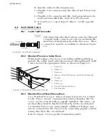
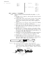
F) Strip the PVC jacket and shielding back approximately 4
1/2 inches (114,3mm) on the seven-conductor cable.
G) Strip the wire 3/8 inch (9,5mm) on each lead.
H) Pull the Shield wire back against the PVC jacket and
slide and shrink a piece of 3/8 inch W. X 1 inch L. heat-
shrink over the cable as shown in Figure 4-12:
.
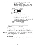
I) Secure the seven-conductor cable to the frame using a
conductive Clamp. Ensure that the Clamp and Shield
wire come in contact with one another. Refer to Figure
4-13:.
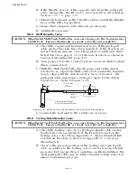
12.
Throttle: TB8
Brown - 3,
Red - 4,
Orange - 5,
White - 6,
Black - 7
10
Clutch: TB11
Black - 1
Brown - 2
Yellow - 5
Green - 6
10 & 11. Clutch/Troll: TB11
Black - 1
Brown - 2
Red - 3
Orange - 4
Yellow - 5
Green - 6
Blue - 7
White - 8
Figure 4-12: Seven-Conductor Control Head Cable Shield Wire and Heat-Shrink
Figure 4-13: Clamp Views
12266A
(CLAMP)
(FRAME)
(CLAMP)
(FRAME)
Top View
Side View
Содержание ClearCommand 9000 Series
Страница 1: ...ClearCommand 9000 Series Installation Operation and Troubleshooting Manual MM9000 I Rev C 2 5 08...
Страница 132: ......
Страница 133: ...APPENDIX A...
Страница 134: ......
Страница 139: ......
Страница 140: ...Page A 4...
Страница 143: ......
Страница 144: ...10...
Страница 148: ...Page A 18...
Страница 149: ...Page A 19 TEMPLATE...
Страница 150: ...Page A 20...
Страница 152: ...Page A 22...
Страница 154: ...Page A 24...
Страница 156: ...Page A 26...
Страница 157: ...Page A 27 Drawing 11488D 1 Twin Screw Single APS Connection Alternate Remote Switch...
Страница 158: ...Page A 28...
Страница 159: ...Page A 29 Drawing 11488D 2 Twin Screw Dual APS Connections...
Страница 160: ...Page A 30...
Страница 161: ...Page A 31 Drawing 11488D 3 APS Notes Page...
Страница 162: ...Page A 32...
Страница 164: ...Page A 34...
Страница 166: ...Page A 36...
Страница 170: ...Page A 40...
Страница 172: ...Page A 42...
Страница 176: ...Page A 46...
Страница 178: ...Page C 48 ZF Mathers LLC 12125 Harbour Reach Drive Suite B Mukilteo WA 98275...
Страница 179: ...APPENDIX B...
Страница 180: ......
Страница 234: ...Appendix B 6...
Страница 238: ...Appendix B 10...
Страница 242: ...Appendix B 14...
Страница 247: ...Service Field Test Unit Reference Manual MM13927 Rev E 4 07...
Страница 248: ......
Страница 250: ...Page ii Table of Contents...
Страница 264: ...SERVICE FIELD TEST UNIT MM13927 RvD 10 03 Page 3 2...
Страница 265: ...APPENDIX C...
Страница 266: ......
Страница 267: ...Appendix C 1 Drawing 12284A 1 ClearCommand Diagram all options...
Страница 268: ...Appendix C 2...
Страница 269: ...Appendix C 3 Drawing 12284A 2 ClearCommand Circuit Board Connections...
Страница 270: ...Appendix C 4...
Страница 271: ...Appendix C 5 Drawing 12284A 3 ClearCommand Drawing Notes Page...
Страница 272: ...Appendix C 6...