


TROUBLESHOOTING
PageB5-2
should be greater than 12.4 Volts in 12 VDC systems and
24.8 Volts in 24 VDC systems. If not, the battery or it’s
charging system needs servicing.
D) The voltage differential between the power source and the
Processor should not exceed 1.2 Volts in 12 VDC systems
and 2.4 Volts in 24 VDC systems. If so, there is high resis-
tance somewhere between the battery and Processor.
E) High resistance, resulting in a differential voltage of 1.2
Volts (12 VDC Systems) or 2.4 Volts (24 VDC Systems) or
greater, may be the result of corroded or tarnished connec-
tions, dirty or pitted relay contacts or an improperly sized
power cable.
F) If the voltage differential is less than 1.2 Volts (12 VDC Sys-
tems) or 2.4 Volts (24 VDC Systems), which is what you
would typically expect, a loose connection may exist
between the power source and the Processor. The vibra-
tion experienced while the vessel is underway may inter-
mittently cause the circuit to open. Check all the
connections between the power source and the Processor
for a loose bolts, nuts, etc.
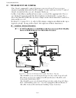
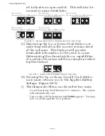
B5-1.2 One Long - Three Short Tones
This tone indicates that there is an invalid command signal at the
Station-in-Command.
The Processor expects a DC voltage, representative of the Control
Head’s present lever position. This voltage is referred to as the
“Command Signal”. In normally functioning Control Heads, the
command signal is between approximately 0.8VDC at Full Astern
to 4.10 VDC at Full Ahead.
The command signal is converted by the Processor to a digital
representation, referred to as an A/D Count. More on A/D
Counts later. If the command signal drops below 0.6VDC or
exceeds 4.40 VDC, the tone will be generated.
At the same time the tone is heard, throttle command drops to
Idle and the clutch will be commanded to Neutral. The following
items will cause this to occur:
• An open or high resistance connection between the Control Head
and Processor.
• Out of calibration Control Head.
• A defective Control Head.
• A defective A/D Converter in the Processor.
The exact cause of the malfunction can be found as follows:
NOTE: I
F
AN
APS
IS
BEING
UTILIZED
IN
THE
POWER
CIRCUIT
,
TAKE
INTO
ACCOUNT
THE
0.7 VDC
FOR
-
WARD
VOLTAGE
DROP
OF
THE
DIODES
. T
HIS
WOULD
INCREASE
THE
PERMISSIBLE
DIFFERENTIAL
BETWEEN
POWER
SOURCE
AND
P
ROCESSOR
FROM
1.2
TO
1.9 VDC
IN
12 VDC
CIRCUITS
AND
2.4
TO
3.1 VDC
IN
24 VDC
CIRCUITS
.
Figure B5-15: One Long - Three Short Tones
Содержание ClearCommand 9000 Series
Страница 1: ...ClearCommand 9000 Series Installation Operation and Troubleshooting Manual MM9000 I Rev C 2 5 08...
Страница 132: ......
Страница 133: ...APPENDIX A...
Страница 134: ......
Страница 139: ......
Страница 140: ...Page A 4...
Страница 143: ......
Страница 144: ...10...
Страница 148: ...Page A 18...
Страница 149: ...Page A 19 TEMPLATE...
Страница 150: ...Page A 20...
Страница 152: ...Page A 22...
Страница 154: ...Page A 24...
Страница 156: ...Page A 26...
Страница 157: ...Page A 27 Drawing 11488D 1 Twin Screw Single APS Connection Alternate Remote Switch...
Страница 158: ...Page A 28...
Страница 159: ...Page A 29 Drawing 11488D 2 Twin Screw Dual APS Connections...
Страница 160: ...Page A 30...
Страница 161: ...Page A 31 Drawing 11488D 3 APS Notes Page...
Страница 162: ...Page A 32...
Страница 164: ...Page A 34...
Страница 166: ...Page A 36...
Страница 170: ...Page A 40...
Страница 172: ...Page A 42...
Страница 176: ...Page A 46...
Страница 178: ...Page C 48 ZF Mathers LLC 12125 Harbour Reach Drive Suite B Mukilteo WA 98275...
Страница 179: ...APPENDIX B...
Страница 180: ......
Страница 234: ...Appendix B 6...
Страница 238: ...Appendix B 10...
Страница 242: ...Appendix B 14...
Страница 247: ...Service Field Test Unit Reference Manual MM13927 Rev E 4 07...
Страница 248: ......
Страница 250: ...Page ii Table of Contents...
Страница 264: ...SERVICE FIELD TEST UNIT MM13927 RvD 10 03 Page 3 2...
Страница 265: ...APPENDIX C...
Страница 266: ......
Страница 267: ...Appendix C 1 Drawing 12284A 1 ClearCommand Diagram all options...
Страница 268: ...Appendix C 2...
Страница 269: ...Appendix C 3 Drawing 12284A 2 ClearCommand Circuit Board Connections...
Страница 270: ...Appendix C 4...
Страница 271: ...Appendix C 5 Drawing 12284A 3 ClearCommand Drawing Notes Page...
Страница 272: ...Appendix C 6...