


OPERATION
Page 2-1
2
OPERATION
2-1
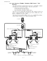
DC P
OWER
O
N
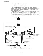
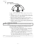
When DC power is turned ON to the Processor:
• A short steady tone, followed by an intermittent tone, will sound at
all Remote Stations indicating that no station has command.
• The Start Interlock relay contact will remain open, preventing
engine start.
• Throttle:
Servo: The throttle servo will drive to Idle.
Electric: The throttle signal will be commanded to Idle.
• Shift:
Servo: The Shift servo will drive to Neutral.
Solenoid: The Ahead and Astern shift solenoids will be de-ener-
gized, commanding Neutral.
• Troll:
Servo: The trolling valve servo will drive to lock-up.
Solenoid: The trolling valve solenoids are commanding lock-up.
2-2
T
AKING
C
OMMAND
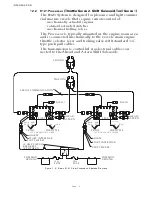
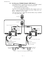
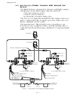
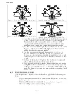
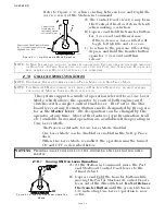
To take command at any one of the up to five Remote Stations:
• Ensure all Control Head’s lever(s) at that Station are in the Neutral
detent (vertical position)
• Depress the transfer button for 1/2 second.
The Slow Repetitive tone will stop at all Stations, and the red LED
indicator light will turn ON at the Control Head of the Station that
had assumed command of the Control System.
Figure 2-1: Station taking Command
NOTE: I
F
S
TART
I
NTERLOCK
IS
USED
: O
NCE
A
S
TATION
IS
IN
COMMAND
THE
S
TART
I
NTERLOCK
RELAY
CONTACT
WILL
CLOSE
,
ALLOWING
THE
ENGINE
TO
START
.
NOTE: O
NLY
ONE
S
TATION
CAN
HAVE
COMMAND
AT
A
TIME
.
Содержание ClearCommand 9000 Series
Страница 1: ...ClearCommand 9000 Series Installation Operation and Troubleshooting Manual MM9000 I Rev C 2 5 08...
Страница 132: ......
Страница 133: ...APPENDIX A...
Страница 134: ......
Страница 139: ......
Страница 140: ...Page A 4...
Страница 143: ......
Страница 144: ...10...
Страница 148: ...Page A 18...
Страница 149: ...Page A 19 TEMPLATE...
Страница 150: ...Page A 20...
Страница 152: ...Page A 22...
Страница 154: ...Page A 24...
Страница 156: ...Page A 26...
Страница 157: ...Page A 27 Drawing 11488D 1 Twin Screw Single APS Connection Alternate Remote Switch...
Страница 158: ...Page A 28...
Страница 159: ...Page A 29 Drawing 11488D 2 Twin Screw Dual APS Connections...
Страница 160: ...Page A 30...
Страница 161: ...Page A 31 Drawing 11488D 3 APS Notes Page...
Страница 162: ...Page A 32...
Страница 164: ...Page A 34...
Страница 166: ...Page A 36...
Страница 170: ...Page A 40...
Страница 172: ...Page A 42...
Страница 176: ...Page A 46...
Страница 178: ...Page C 48 ZF Mathers LLC 12125 Harbour Reach Drive Suite B Mukilteo WA 98275...
Страница 179: ...APPENDIX B...
Страница 180: ......
Страница 234: ...Appendix B 6...
Страница 238: ...Appendix B 10...
Страница 242: ...Appendix B 14...
Страница 247: ...Service Field Test Unit Reference Manual MM13927 Rev E 4 07...
Страница 248: ......
Страница 250: ...Page ii Table of Contents...
Страница 264: ...SERVICE FIELD TEST UNIT MM13927 RvD 10 03 Page 3 2...
Страница 265: ...APPENDIX C...
Страница 266: ......
Страница 267: ...Appendix C 1 Drawing 12284A 1 ClearCommand Diagram all options...
Страница 268: ...Appendix C 2...
Страница 269: ...Appendix C 3 Drawing 12284A 2 ClearCommand Circuit Board Connections...
Страница 270: ...Appendix C 4...
Страница 271: ...Appendix C 5 Drawing 12284A 3 ClearCommand Drawing Notes Page...
Страница 272: ...Appendix C 6...


