


TROUBLESHOOTING
PageB4-1
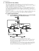
B4 TROUBLESHOOTING DIAGNOSTIC MENU
The Processor has built in diagnostics designed to assist
the technician in determining the cause of a problem.
The following information is available to view at any
time:
• Applied Battery Voltage
• Tachometer Sender Frequency
• Stations 1- 5 A/D’s
• Stations 1- 5 Transfer Button Status
• Servo 2 Feedback A/D’s
• Servo 1 Feedback A/D’s
• Software Revision Level
In order to access this information, follow the steps
below:
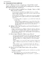
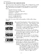
Figure B4-6: Display Function
Code List
Figure B4-7: Display
Troubleshooting Function
Figure B4-8: Display
Troubleshooting Function Blinking
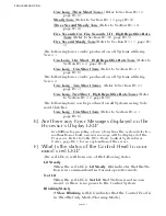
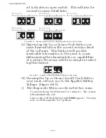
Figure B4-9: Example Display of
Applied Battery Voltage
A)Locate the Display LED on the Port or
Starboard Processor. The Display LED
will have the Processor Part Number
displayed in a running pattern moving
from left to right while the program is
running in Normal Operation.
B) Depress the Up or Down Push Button
to activate the Function Code List. The
characters A001 will be shown on the
Display like Figure B4-6:
C)Depress the Up or Down Push Button
repeatedly until H000 is displayed like
Figure B4-7:.
D)Depress and hold the Left and Right
Push Buttons simultaneously until the
H0 begins to blink. (Figure B4-8:)
Release the Push Buttons; the applied
battery voltage will now be displayed:
• The displayed value is in “real time”
and provides a rough estimate of the
DC voltage applied to the Processor.
The reading is accurate to within
0.50 DC. Refer to Figure B4-9:
Function Code is Blinking
Содержание ClearCommand 9000 Series
Страница 1: ...ClearCommand 9000 Series Installation Operation and Troubleshooting Manual MM9000 I Rev C 2 5 08...
Страница 132: ......
Страница 133: ...APPENDIX A...
Страница 134: ......
Страница 139: ......
Страница 140: ...Page A 4...
Страница 143: ......
Страница 144: ...10...
Страница 148: ...Page A 18...
Страница 149: ...Page A 19 TEMPLATE...
Страница 150: ...Page A 20...
Страница 152: ...Page A 22...
Страница 154: ...Page A 24...
Страница 156: ...Page A 26...
Страница 157: ...Page A 27 Drawing 11488D 1 Twin Screw Single APS Connection Alternate Remote Switch...
Страница 158: ...Page A 28...
Страница 159: ...Page A 29 Drawing 11488D 2 Twin Screw Dual APS Connections...
Страница 160: ...Page A 30...
Страница 161: ...Page A 31 Drawing 11488D 3 APS Notes Page...
Страница 162: ...Page A 32...
Страница 164: ...Page A 34...
Страница 166: ...Page A 36...
Страница 170: ...Page A 40...
Страница 172: ...Page A 42...
Страница 176: ...Page A 46...
Страница 178: ...Page C 48 ZF Mathers LLC 12125 Harbour Reach Drive Suite B Mukilteo WA 98275...
Страница 179: ...APPENDIX B...
Страница 180: ......
Страница 234: ...Appendix B 6...
Страница 238: ...Appendix B 10...
Страница 242: ...Appendix B 14...
Страница 247: ...Service Field Test Unit Reference Manual MM13927 Rev E 4 07...
Страница 248: ......
Страница 250: ...Page ii Table of Contents...
Страница 264: ...SERVICE FIELD TEST UNIT MM13927 RvD 10 03 Page 3 2...
Страница 265: ...APPENDIX C...
Страница 266: ......
Страница 267: ...Appendix C 1 Drawing 12284A 1 ClearCommand Diagram all options...
Страница 268: ...Appendix C 2...
Страница 269: ...Appendix C 3 Drawing 12284A 2 ClearCommand Circuit Board Connections...
Страница 270: ...Appendix C 4...
Страница 271: ...Appendix C 5 Drawing 12284A 3 ClearCommand Drawing Notes Page...
Страница 272: ...Appendix C 6...