


PLAN THE INSTALLATION
Page3-2
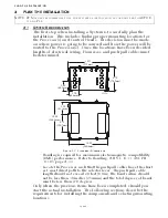
3-1.1 Processor(s)
Processors required per engine:
Single Screw: One (1) Processor
Twin Screw: Two (2) Processors
Mounting Hardware is installer supplied.
Installation/Troubleshooting Manual is included with the Proces-
sor.
The following items must be taken into account when selecting
the location for the Processor(s):
• The Processor is spray proof, but not water proof. Therefore,
an area must be selected that typically stays dry.
• The engine room is the preferred location for mounting the
Processor.
• If the engine room is too small, locate in any area where it is
easily accessible, as long as all of the criteria listed are met.
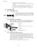
• Bulkhead mounting is the preferred method due to ease of
access for wiring and adjustments. However, the Processor
can be mounted in any attitude as long as the Display LED
window and push buttons are accessible.
• Do not mount the Processor on the engine, transmission, or in
any location that will subject it to excessive vibration.
• Do not mount the Processor to the transom when the vessel is
equipped with a surface piercing drive system, due to vibra-
tion concerns.
• Locate the Processor(s) away from sources of high heat, such
as an engine exhaust manifolds or turbochargers. Allow 4 feet
(1,2m) of clearance or more.
• Do not mount the Processor(s) in close proximity to gas engine
ignition systems, alternators, generators or any equipment
producing strong magnetic fields. Allow 4 feet (1,2m) clear-
ance or more.
3-1.2 Control Head(s)
Refer to Appendix A - Control Head Variations Service Sheets for
information on the various Control Heads available and their
dimensions.
• The 400 and MC2000 Series Control Heads are spray proof
from the top, but must be protected from the weather on the
underside.
• The 700 Series Control Heads are fully water proof.
• Control Heads are available with pluggable pigtails or may be
hard-wired (no pigtails).
• When a 400 or MC2000 Series Control Head must be mounted
in a location where the underside may be exposed to the
CAUTION: Strong magnetic fields can influence the Processor’s electronic circuits
and void your warranty.
Содержание ClearCommand 9000 Series
Страница 1: ...ClearCommand 9000 Series Installation Operation and Troubleshooting Manual MM9000 I Rev C 2 5 08...
Страница 132: ......
Страница 133: ...APPENDIX A...
Страница 134: ......
Страница 139: ......
Страница 140: ...Page A 4...
Страница 143: ......
Страница 144: ...10...
Страница 148: ...Page A 18...
Страница 149: ...Page A 19 TEMPLATE...
Страница 150: ...Page A 20...
Страница 152: ...Page A 22...
Страница 154: ...Page A 24...
Страница 156: ...Page A 26...
Страница 157: ...Page A 27 Drawing 11488D 1 Twin Screw Single APS Connection Alternate Remote Switch...
Страница 158: ...Page A 28...
Страница 159: ...Page A 29 Drawing 11488D 2 Twin Screw Dual APS Connections...
Страница 160: ...Page A 30...
Страница 161: ...Page A 31 Drawing 11488D 3 APS Notes Page...
Страница 162: ...Page A 32...
Страница 164: ...Page A 34...
Страница 166: ...Page A 36...
Страница 170: ...Page A 40...
Страница 172: ...Page A 42...
Страница 176: ...Page A 46...
Страница 178: ...Page C 48 ZF Mathers LLC 12125 Harbour Reach Drive Suite B Mukilteo WA 98275...
Страница 179: ...APPENDIX B...
Страница 180: ......
Страница 234: ...Appendix B 6...
Страница 238: ...Appendix B 10...
Страница 242: ...Appendix B 14...
Страница 247: ...Service Field Test Unit Reference Manual MM13927 Rev E 4 07...
Страница 248: ......
Страница 250: ...Page ii Table of Contents...
Страница 264: ...SERVICE FIELD TEST UNIT MM13927 RvD 10 03 Page 3 2...
Страница 265: ...APPENDIX C...
Страница 266: ......
Страница 267: ...Appendix C 1 Drawing 12284A 1 ClearCommand Diagram all options...
Страница 268: ...Appendix C 2...
Страница 269: ...Appendix C 3 Drawing 12284A 2 ClearCommand Circuit Board Connections...
Страница 270: ...Appendix C 4...
Страница 271: ...Appendix C 5 Drawing 12284A 3 ClearCommand Drawing Notes Page...
Страница 272: ...Appendix C 6...