


SEA TRIALS
Page7-9
F) If twin screw, repeat steps A) through E) on the opposite
side.
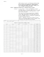
7-15.3 Troll Throttle Limit Adjustment (Function Code L4)
•
The Value programmed for Function Code
L4
is a percentage of
the throttle range. The Throttle Range is the difference between
Throttle Maximum (
E3
) and Throttle Minimum (
E2
).
• The maximum percentage of the Throttle Range which the Value
can be set to is
20
%.
• The adjustment of this Function Code is a matter of personal
preference. There is not set procedure which determines when
increased throttle should be used and what percentage of the
range it should be set to.
7-15.4 Troll Pulse Duration (Function Code
L5
) & Troll Pulse Percentage
(Function Code
L6
) Adjustments
Whenever Troll is enabled (red LED blinking rapidly) and the
Control Head lever is moved from Neutral/Idle to the Ahead or
Astern detent, the current to the Proportional Solenoid is deliv-
ered at a value which causes a higher clutch pressure for a set
period of time. The period of time where the higher pressure is
commanded is adjustable with this Function.
The default Value of
00.6
seconds has been found to be adequate
with most applications. However, if the shaft takes unreasonably
long to begin rotating, or if an excessive surge is felt when com-
manding Ahead with Troll selected, the amount of time that the
higher pressure is commanded may be adjusted with the Troll
Pulse Duration Function.
The Troll Pulse Percentage’s Value automatically changes to the
same Value selected with Troll Maximum (Function Code
L3
).
As with Troll Pulse Duration, experience has showed us that
commanding this higher clutch pressure is adequate in most
applications. In the event that the shaft takes unreasonably long
to begin to rotate, or an excessive surge is produced every time
Ahead is commanded with Troll, the Value can be increased or
decreased.
When the need to adjust these Values arises, it is recommended
that small adjustments to each of these Functions are made
instead of one large adjustment to one or the other. After each
small adjustment, test the vessel’s response prior to making fur-
ther adjustments.
NOTE: O
N
T
WIN
S
CREW
APPLICATIONS
,
THE
T
ROLL
M
INIMUM
AND
T
ROLL
M
AXIMUM
PRESSURE
ADJUSTMENTS
SHOULD
BE
DONE
ONE
SIDE
AT
A
TIME
INITIALLY
. O
NCE
EACH
T
ROLLING
V
ALVE
HAS
BEEN
ADJUSTED
INDIVIDUALLY
,
THEY
MUST
BE
OPERATED
AS
A
PAIR
AND
ADJUSTED
FUR
-
THER
,
AS
NECESSARY
.
CAUTION: Consult the Trolling Valve’s Installation Manual prior to programming any
increased throttle above Idle, while slipping the Clutch. Failure to adhere to
the Transmission manufactures directives may permanently damage the
clutch pack and void the warranty.
Содержание ClearCommand 9000 Series
Страница 1: ...ClearCommand 9000 Series Installation Operation and Troubleshooting Manual MM9000 I Rev C 2 5 08...
Страница 132: ......
Страница 133: ...APPENDIX A...
Страница 134: ......
Страница 139: ......
Страница 140: ...Page A 4...
Страница 143: ......
Страница 144: ...10...
Страница 148: ...Page A 18...
Страница 149: ...Page A 19 TEMPLATE...
Страница 150: ...Page A 20...
Страница 152: ...Page A 22...
Страница 154: ...Page A 24...
Страница 156: ...Page A 26...
Страница 157: ...Page A 27 Drawing 11488D 1 Twin Screw Single APS Connection Alternate Remote Switch...
Страница 158: ...Page A 28...
Страница 159: ...Page A 29 Drawing 11488D 2 Twin Screw Dual APS Connections...
Страница 160: ...Page A 30...
Страница 161: ...Page A 31 Drawing 11488D 3 APS Notes Page...
Страница 162: ...Page A 32...
Страница 164: ...Page A 34...
Страница 166: ...Page A 36...
Страница 170: ...Page A 40...
Страница 172: ...Page A 42...
Страница 176: ...Page A 46...
Страница 178: ...Page C 48 ZF Mathers LLC 12125 Harbour Reach Drive Suite B Mukilteo WA 98275...
Страница 179: ...APPENDIX B...
Страница 180: ......
Страница 234: ...Appendix B 6...
Страница 238: ...Appendix B 10...
Страница 242: ...Appendix B 14...
Страница 247: ...Service Field Test Unit Reference Manual MM13927 Rev E 4 07...
Страница 248: ......
Страница 250: ...Page ii Table of Contents...
Страница 264: ...SERVICE FIELD TEST UNIT MM13927 RvD 10 03 Page 3 2...
Страница 265: ...APPENDIX C...
Страница 266: ......
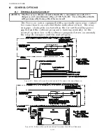
Страница 267: ...Appendix C 1 Drawing 12284A 1 ClearCommand Diagram all options...
Страница 268: ...Appendix C 2...
Страница 269: ...Appendix C 3 Drawing 12284A 2 ClearCommand Circuit Board Connections...
Страница 270: ...Appendix C 4...
Страница 271: ...Appendix C 5 Drawing 12284A 3 ClearCommand Drawing Notes Page...
Страница 272: ...Appendix C 6...