


TROUBLESHOOTING
Page B6-1
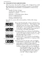
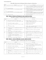
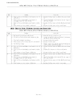
B6 TROUBLESHOOTING STATION TRANSFER
In order to transfer command from one Remote Station to another,
the following must occur:
•
There must be a valid “Command Signal” at the Station being
transferred to.
• The “Command Signal” must indicate that the Control Head’s
lever(s) is at the Neutral/Idle position.
• The Transfer Button must be depressed which takes the “Station
Select” signal from 5.00 VDC to 0.00 VDC.
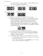
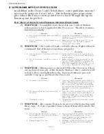
If a transfer from one Remote Station to another is requested, but
does not take place; the items required for successful transfer can
be tested as follows:
B6-1 C
OMMAND
S
IGNAL
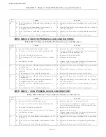
The Command Signal is a DC voltage which varies in relationship
to the Control Head’s lever position.
The Processor provides each Control Head 5.00 +/- 0.20VDC,
which is referred to as the “Reference Voltage”.
The Reference Voltage is applied to a 5K Ohm Potentiometer in the
Control Head.
The potentiometer’s “Wiper” taps off a portion of the Reference
Voltage and sends it back to the Processor.
The amount of DC voltage which is tapped off, is dependant on the
position of the Control Head’s lever.
When the lever is fully Astern, a small portion of the Reference
Voltage is tapped off by the wiper, and therefore, the volt-
age is at its lowest point (approximately 0.80 VDC).
When the lever is positioned fully Ahead, a larger portion is tapped
off and the voltage is at its highest point (approximately
4.10 VDC).
B6-2 A
TO
D C
OUNTS
Since all the calculations within the control system are performed
digitally, these DC voltages are expressed as and converted to a dig-
ital representation.
• The “Reference Voltage” (approximately 5.00 VDC) by which all
analog inputs are based, is represented as 1023 A/D (Analog to
Digital) Counts.
• This allows for the possibility of a 1024 possible positions when 0
is included in the count.
• The value of the Command Voltage with the lever at the Neutral/
Idle position is 49- 51% of the Reference Voltage when measured
at the Station terminal block. The actual value read by the Proces-
sor is 2% below that value or 47% to 49% of 1023 A/D Counts (485-
505 A/D).
Содержание ClearCommand 9000 Series
Страница 1: ...ClearCommand 9000 Series Installation Operation and Troubleshooting Manual MM9000 I Rev C 2 5 08...
Страница 132: ......
Страница 133: ...APPENDIX A...
Страница 134: ......
Страница 139: ......
Страница 140: ...Page A 4...
Страница 143: ......
Страница 144: ...10...
Страница 148: ...Page A 18...
Страница 149: ...Page A 19 TEMPLATE...
Страница 150: ...Page A 20...
Страница 152: ...Page A 22...
Страница 154: ...Page A 24...
Страница 156: ...Page A 26...
Страница 157: ...Page A 27 Drawing 11488D 1 Twin Screw Single APS Connection Alternate Remote Switch...
Страница 158: ...Page A 28...
Страница 159: ...Page A 29 Drawing 11488D 2 Twin Screw Dual APS Connections...
Страница 160: ...Page A 30...
Страница 161: ...Page A 31 Drawing 11488D 3 APS Notes Page...
Страница 162: ...Page A 32...
Страница 164: ...Page A 34...
Страница 166: ...Page A 36...
Страница 170: ...Page A 40...
Страница 172: ...Page A 42...
Страница 176: ...Page A 46...
Страница 178: ...Page C 48 ZF Mathers LLC 12125 Harbour Reach Drive Suite B Mukilteo WA 98275...
Страница 179: ...APPENDIX B...
Страница 180: ......
Страница 234: ...Appendix B 6...
Страница 238: ...Appendix B 10...
Страница 242: ...Appendix B 14...
Страница 247: ...Service Field Test Unit Reference Manual MM13927 Rev E 4 07...
Страница 248: ......
Страница 250: ...Page ii Table of Contents...
Страница 264: ...SERVICE FIELD TEST UNIT MM13927 RvD 10 03 Page 3 2...
Страница 265: ...APPENDIX C...
Страница 266: ......
Страница 267: ...Appendix C 1 Drawing 12284A 1 ClearCommand Diagram all options...
Страница 268: ...Appendix C 2...
Страница 269: ...Appendix C 3 Drawing 12284A 2 ClearCommand Circuit Board Connections...
Страница 270: ...Appendix C 4...
Страница 271: ...Appendix C 5 Drawing 12284A 3 ClearCommand Drawing Notes Page...
Страница 272: ...Appendix C 6...