


INTRODUCTION
Page 1-1
1
INTRODUCTION
This manual is written to document every possible system option.
Your system may not include every available option for single or
twin screw reverse reduction gear applications.
Only those sections that apply to your specific installation are rele-
vant to your vessel.
If additional options described within this manual are desired, con-
tact your dealer for availability/compatibility with your system.
1-1 M
ANUAL
C
ONTENTS
This manual is divided into 12 Sections which cover, in detail, the
features and operation of your system:
• Introduction (Section 1)
• Operation (Section 2)
• Plan the Installation (Section 3)
• Installation (Section 4)
• Set Up Procedures (Section 5)
• Dock Trials (Section 6)
• Sea Trials (Section 7)
• Control Options (Section 8)
• Periodic Checks and Maintenance (Section 9)
• ZF Mathers Service Sheets (Appendix A)
• Troubleshooting (Appendix B)
• General System Drawings (Appendix C)
1-2 B
ASIC
T
HEORY
OF
O
PERATION
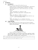
The ClearCommand Marine Propulsion Control System (hereafter
referred to as ClearCommand or System) is electronic and requires
a 12 or 24 VDC power supply, one Processor per engine/clutch and
one Control Head per remote station. The ClearCommand com-
mands the vessel’s throttle and shift using a single Control Head
lever.
One electric cable per Control Head lever connects the remote sta-
tion(s) to the Processor(s). Only one remote station will have com-
mand at a given time and the Station-in-Command is indicated by a
red light located on the Control Head. Station transfer is accom-
plished by pressing the Control Head mounted transfer button
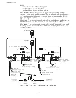
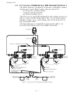
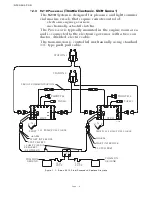
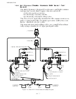
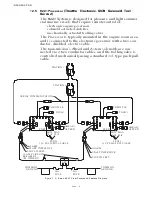
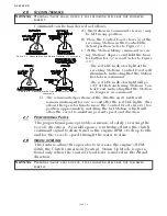
1-2.1
9120 Processor
(Throttle-Servo 2, Shift-Solenoid)
or 9122
Processor
(Throttle-Servo 2, Shift-Solenoid, Troll-Solenoid)
The
9120
or
9122
System is designed for pleasure and light
commercial marine vessels that require remote control of:
9120
• mechanically actuated engines
• solenoid activated clutches.
Содержание ClearCommand 9000 Series
Страница 1: ...ClearCommand 9000 Series Installation Operation and Troubleshooting Manual MM9000 I Rev C 2 5 08...
Страница 132: ......
Страница 133: ...APPENDIX A...
Страница 134: ......
Страница 139: ......
Страница 140: ...Page A 4...
Страница 143: ......
Страница 144: ...10...
Страница 148: ...Page A 18...
Страница 149: ...Page A 19 TEMPLATE...
Страница 150: ...Page A 20...
Страница 152: ...Page A 22...
Страница 154: ...Page A 24...
Страница 156: ...Page A 26...
Страница 157: ...Page A 27 Drawing 11488D 1 Twin Screw Single APS Connection Alternate Remote Switch...
Страница 158: ...Page A 28...
Страница 159: ...Page A 29 Drawing 11488D 2 Twin Screw Dual APS Connections...
Страница 160: ...Page A 30...
Страница 161: ...Page A 31 Drawing 11488D 3 APS Notes Page...
Страница 162: ...Page A 32...
Страница 164: ...Page A 34...
Страница 166: ...Page A 36...
Страница 170: ...Page A 40...
Страница 172: ...Page A 42...
Страница 176: ...Page A 46...
Страница 178: ...Page C 48 ZF Mathers LLC 12125 Harbour Reach Drive Suite B Mukilteo WA 98275...
Страница 179: ...APPENDIX B...
Страница 180: ......
Страница 234: ...Appendix B 6...
Страница 238: ...Appendix B 10...
Страница 242: ...Appendix B 14...
Страница 247: ...Service Field Test Unit Reference Manual MM13927 Rev E 4 07...
Страница 248: ......
Страница 250: ...Page ii Table of Contents...
Страница 264: ...SERVICE FIELD TEST UNIT MM13927 RvD 10 03 Page 3 2...
Страница 265: ...APPENDIX C...
Страница 266: ......
Страница 267: ...Appendix C 1 Drawing 12284A 1 ClearCommand Diagram all options...
Страница 268: ...Appendix C 2...
Страница 269: ...Appendix C 3 Drawing 12284A 2 ClearCommand Circuit Board Connections...
Страница 270: ...Appendix C 4...
Страница 271: ...Appendix C 5 Drawing 12284A 3 ClearCommand Drawing Notes Page...
Страница 272: ...Appendix C 6...


