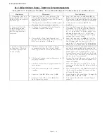
TROUBLESHOOTING
Page B13-1
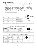
B13 PROCESSOR PIGTAILS
The number and types of Pigtails used varies with the
different Processors and their configurations. The basic
off-the-shelf Processors are available with no Pigtails
(hard-wired) or pre-wired for for up to a total of eight
Pigtails when all five Remote Stations are being used.
The following Tables describe the pin outs and functions
of the conductors within the various Pigtails.
B13-1B
ASIC
P
ROCESSOR
P
IGTAILS
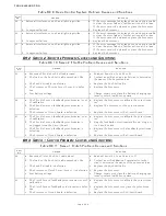
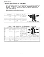
Table B13-1: Power, Start Interlock, Clutch Oil Pressure Switch, and Alarm Pigtail Pin-Out
CIRCUIT BOARD
PLUG
Figure B13-1: Power, Start Interlock,
Clutch Oil Pressure, and Alarm Pigtail
Pin Out
Termination A Conductor Color Termination
B
Description
PB2-2
Yellow
Pin 1
Start Interlock
TB6-6
Brown
Pin 2
Alarm (N.O.)
TB6-5
Black
Pin 3
Alarm (Common)
TB6-2
Orange
Pin 4
Back-up Ctrl (Ground)
TB6-1
White
Pin 5
Back-up Ctrl Input
TB6-3
Blue
Pin 6
Clutch Pressure Switch
TB6-4
Green
Pin 7
Clutch Pressure Switch (Ground)
PB1 (+)
Red
Pin 10
DC Power (+)
PB1 (-)
Black
Pin 11
DC Power (-)
PB2-1
Red
Pin 12
Start Interlock
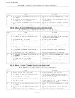
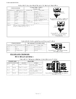
Table B13-2: Serial Communication Pigtail Pin-Out
CIRCUIT BOARD
PLUG
Figure B13-2: Serial Communication
Pigtail Pin Out
Termination A
Conductor Color
Termination B
Description
TB7-6
White
Pin 2
CAN High
TB7-7
Green
Pin 1
CAN Low
TB7-8
Red
Pin 4
CAN High
TB7-9
Black
Pin 5
CAN Low
TB7-10
Black
Pin 6
Shield
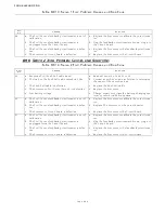
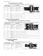
Table B13-3: Control Head Pigtail Pin-Out (Up to 5 Stations)
CIRCUIT BOARD
PLUG
Figure B13-3: Control Head Pigtail Pin
Out
Termination A Conductor Color Termination B
Description
Frame
Non-insulated to
Green/ Yellow
Pin 1
Shield
TB1 thru 5-2 Brown
Pin 2
Red LED (+)
TB1 thru 5-8 Violet
Pin 3
Green LED (-)
TB1 thru 5-4 Orange
Pin 4
Transfer Button
TB1 thru 5-3 Red
Pin 5
Ground
TB1 thru 5-7 Blue
Pin 7
VREF (+5VDC)
TB1 thru 5-6 Green
Pin 6
Lever Command Signal
TB1 thru 5-1 Black
Pin 8
Tone (+)
1
2
3
4
5
6
7
8
9
1
0
11
1
2
1 - Yellow
2 - Brown
3 - Black
4 - Orange
5 - White
6 - Blue
12 - Red
11 - Black
10 - Red
7- Green
2-Conductor
Cable
6 - Black
2- White
5 - Black
4 - Red
1- Green
1
2
3
4
5
6
6 - Green
8 - Black
2 - Brown
3 - Violet
7 - Blue
1
2
3
4
5
6
7
8
1 - Green/Yellow
5 - Red
4 - Orange
Содержание ClearCommand 9000 Series
Страница 1: ...ClearCommand 9000 Series Installation Operation and Troubleshooting Manual MM9000 I Rev C 2 5 08...
Страница 132: ......
Страница 133: ...APPENDIX A...
Страница 134: ......
Страница 139: ......
Страница 140: ...Page A 4...
Страница 143: ......
Страница 144: ...10...
Страница 148: ...Page A 18...
Страница 149: ...Page A 19 TEMPLATE...
Страница 150: ...Page A 20...
Страница 152: ...Page A 22...
Страница 154: ...Page A 24...
Страница 156: ...Page A 26...
Страница 157: ...Page A 27 Drawing 11488D 1 Twin Screw Single APS Connection Alternate Remote Switch...
Страница 158: ...Page A 28...
Страница 159: ...Page A 29 Drawing 11488D 2 Twin Screw Dual APS Connections...
Страница 160: ...Page A 30...
Страница 161: ...Page A 31 Drawing 11488D 3 APS Notes Page...
Страница 162: ...Page A 32...
Страница 164: ...Page A 34...
Страница 166: ...Page A 36...
Страница 170: ...Page A 40...
Страница 172: ...Page A 42...
Страница 176: ...Page A 46...
Страница 178: ...Page C 48 ZF Mathers LLC 12125 Harbour Reach Drive Suite B Mukilteo WA 98275...
Страница 179: ...APPENDIX B...
Страница 180: ......
Страница 234: ...Appendix B 6...
Страница 238: ...Appendix B 10...
Страница 242: ...Appendix B 14...
Страница 247: ...Service Field Test Unit Reference Manual MM13927 Rev E 4 07...
Страница 248: ......
Страница 250: ...Page ii Table of Contents...
Страница 264: ...SERVICE FIELD TEST UNIT MM13927 RvD 10 03 Page 3 2...
Страница 265: ...APPENDIX C...
Страница 266: ......
Страница 267: ...Appendix C 1 Drawing 12284A 1 ClearCommand Diagram all options...
Страница 268: ...Appendix C 2...
Страница 269: ...Appendix C 3 Drawing 12284A 2 ClearCommand Circuit Board Connections...
Страница 270: ...Appendix C 4...
Страница 271: ...Appendix C 5 Drawing 12284A 3 ClearCommand Drawing Notes Page...
Страница 272: ...Appendix C 6...

