


SEA TRIALS
Page7-4
•
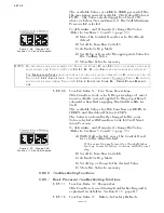
If the engine stalled or came very close to stalling, increase the
Value of Function Code
C3
by one second. Repeat steps A)
through C).
• If the engine does not stall or come close to stalling, proceed with
the next step.
E) Repeat steps A) through D) with the Throttle at 50%, 75%, and
100% of the speed range.
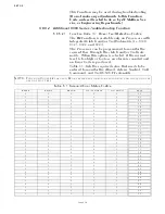
•
If the engine stalls at any time, increase the Value of Function
Code
C3
by one second and repeat the steps A) through D)
again.
F) Once a Full Speed Reversal is successful without coming close
to stalling, the Proportional Pause is properly adjusted.
7-14 S
YNCHRONIZATION
T
EST
(T
WIN
S
CREW
O
NLY
)
7-14.1 Equal Throttle Synchronization
A) Move both Control Head levers side by side to approximately
25% of the Throttle range.
B) If previously disabled, enable the synchronization by depress-
ing the transfer button for two seconds.
• The green LED on the Control Head should illuminate, indicating
synchronization.
C) Check the engine tachometers to see if they are within 1% of
one another.
D) Move both Control Head levers side by side to approximately
50% of the Throttle range.
E) Check the engine tachometers to see if they are within 1% of
one another.
F) Move both Control Head levers side by side to approximately
75% of the Throttle range.
G) Check the engine tachometers to see if they are within 1% of
one another.
H) Move both Control Head levers side by side to 100% of the
Throttle range.
I) Check the engine tachometers to see if they are within 1% of
one another.
• While synchronized, if the tachometers have a greater than 1%
difference at any engine RPM, Active Synchronization is recom-
mended.
7-14.2 Active Synchronization
A) Move both Control Head levers side by side to approximately
25% of the Throttle range.
B) If previously disabled, enable the synchronization by depress-
ing the transfer button for two seconds.
• The green LED on the Control Head may blink while driving
toward synchronization.
Содержание ClearCommand 9000 Series
Страница 1: ...ClearCommand 9000 Series Installation Operation and Troubleshooting Manual MM9000 I Rev C 2 5 08...
Страница 132: ......
Страница 133: ...APPENDIX A...
Страница 134: ......
Страница 139: ......
Страница 140: ...Page A 4...
Страница 143: ......
Страница 144: ...10...
Страница 148: ...Page A 18...
Страница 149: ...Page A 19 TEMPLATE...
Страница 150: ...Page A 20...
Страница 152: ...Page A 22...
Страница 154: ...Page A 24...
Страница 156: ...Page A 26...
Страница 157: ...Page A 27 Drawing 11488D 1 Twin Screw Single APS Connection Alternate Remote Switch...
Страница 158: ...Page A 28...
Страница 159: ...Page A 29 Drawing 11488D 2 Twin Screw Dual APS Connections...
Страница 160: ...Page A 30...
Страница 161: ...Page A 31 Drawing 11488D 3 APS Notes Page...
Страница 162: ...Page A 32...
Страница 164: ...Page A 34...
Страница 166: ...Page A 36...
Страница 170: ...Page A 40...
Страница 172: ...Page A 42...
Страница 176: ...Page A 46...
Страница 178: ...Page C 48 ZF Mathers LLC 12125 Harbour Reach Drive Suite B Mukilteo WA 98275...
Страница 179: ...APPENDIX B...
Страница 180: ......
Страница 234: ...Appendix B 6...
Страница 238: ...Appendix B 10...
Страница 242: ...Appendix B 14...
Страница 247: ...Service Field Test Unit Reference Manual MM13927 Rev E 4 07...
Страница 248: ......
Страница 250: ...Page ii Table of Contents...
Страница 264: ...SERVICE FIELD TEST UNIT MM13927 RvD 10 03 Page 3 2...
Страница 265: ...APPENDIX C...
Страница 266: ......
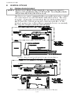
Страница 267: ...Appendix C 1 Drawing 12284A 1 ClearCommand Diagram all options...
Страница 268: ...Appendix C 2...
Страница 269: ...Appendix C 3 Drawing 12284A 2 ClearCommand Circuit Board Connections...
Страница 270: ...Appendix C 4...
Страница 271: ...Appendix C 5 Drawing 12284A 3 ClearCommand Drawing Notes Page...
Страница 272: ...Appendix C 6...