SET UP
Page5-9
5-6.1.2 Function Code
A1
– Number of Engines
5-6.1.3 Function Code
A2
– One Lever Operation
In Twin Screw or more applications, the System has the
ability to command all engines and transmissions to the
same speed and direction with a single Control Head lever.
This Function allows this Feature to be enabled or disabled.
(Refer to Section 2-9, page 2-5,, for operation instructions)
The available Values for this Function are:
00 Disabled (Default Value)
01 Enabled
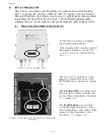
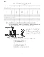
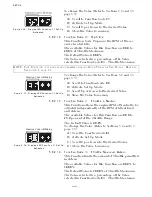
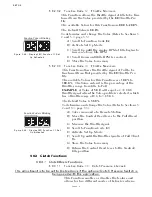
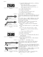
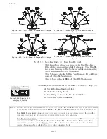
Figure 5-11: Display LED
Function A0 Set Up Activated
To change the Value (Refer to Sections
5-2 and 5-3, page 5-5
):
A) Scroll to Function Code
A0
.
B) Activate Set Up Mode.
C) Scroll Up or Down to the desired Value.
D) Store the Value to memory.
The total number of engines must be entered into the mem-
ory of each of the Processors. All Processors in an installa-
tion must have the same value entered.
The available Values for this Function are:
01 Single Screw (Default Value)
02 Twin Screw
03 Triple Screw
04 Quad Screw
05 Quint Screw
NOTE: T
WIN
SCREW
OR
MORE
APPLICATIONS
REQUIRE
F
UNCTION
C
ODE
A1 V
ALUES
CHANGED
ON
ALL
P
ROCESSORS
PRIOR
TO
CHANGING
THE
V
ALUE
OF
F
UNCTION
C
ODE
A0.
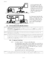
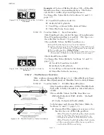
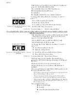
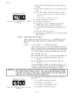
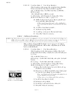
Figure 5-12: Display LED Function
A1 Set Up Activated
To change the Value (Refer to Sections
5-2 and 5-3, page 5-5
):
A) Scroll to Function Code A1.
B) Activate Set Up Mode.
C) Scroll Up or Down to the desired Value.
D)
Store the Value to memory.
NOTE: B
EFORE
CONTINUING
SET
UP
,
WAIT
5
MINUTES
OR
CYCLE
POWER
.
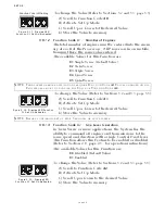
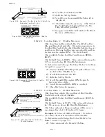
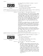
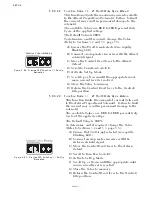
Figure 5-13: Display LED
Function A2 Set Up Activated
To change the Value (Refer to Sections
5-2 and 5-3, page 5-5
):
A) Scroll to Function Code
A2
.
B) Activate Set Up Mode.
C) Scroll Up or Down to the desired Value.
D) Store the Value to memory.
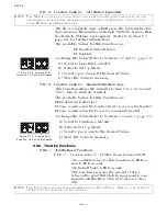
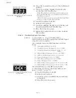
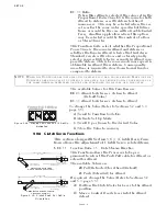
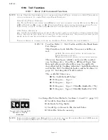
Function Code is Blinking
Содержание ClearCommand 9000 Series
Страница 1: ...ClearCommand 9000 Series Installation Operation and Troubleshooting Manual MM9000 I Rev C 2 5 08...
Страница 132: ......
Страница 133: ...APPENDIX A...
Страница 134: ......
Страница 139: ......
Страница 140: ...Page A 4...
Страница 143: ......
Страница 144: ...10...
Страница 148: ...Page A 18...
Страница 149: ...Page A 19 TEMPLATE...
Страница 150: ...Page A 20...
Страница 152: ...Page A 22...
Страница 154: ...Page A 24...
Страница 156: ...Page A 26...
Страница 157: ...Page A 27 Drawing 11488D 1 Twin Screw Single APS Connection Alternate Remote Switch...
Страница 158: ...Page A 28...
Страница 159: ...Page A 29 Drawing 11488D 2 Twin Screw Dual APS Connections...
Страница 160: ...Page A 30...
Страница 161: ...Page A 31 Drawing 11488D 3 APS Notes Page...
Страница 162: ...Page A 32...
Страница 164: ...Page A 34...
Страница 166: ...Page A 36...
Страница 170: ...Page A 40...
Страница 172: ...Page A 42...
Страница 176: ...Page A 46...
Страница 178: ...Page C 48 ZF Mathers LLC 12125 Harbour Reach Drive Suite B Mukilteo WA 98275...
Страница 179: ...APPENDIX B...
Страница 180: ......
Страница 234: ...Appendix B 6...
Страница 238: ...Appendix B 10...
Страница 242: ...Appendix B 14...
Страница 247: ...Service Field Test Unit Reference Manual MM13927 Rev E 4 07...
Страница 248: ......
Страница 250: ...Page ii Table of Contents...
Страница 264: ...SERVICE FIELD TEST UNIT MM13927 RvD 10 03 Page 3 2...
Страница 265: ...APPENDIX C...
Страница 266: ......
Страница 267: ...Appendix C 1 Drawing 12284A 1 ClearCommand Diagram all options...
Страница 268: ...Appendix C 2...
Страница 269: ...Appendix C 3 Drawing 12284A 2 ClearCommand Circuit Board Connections...
Страница 270: ...Appendix C 4...
Страница 271: ...Appendix C 5 Drawing 12284A 3 ClearCommand Drawing Notes Page...
Страница 272: ...Appendix C 6...


