SEA TRIALS
Page7-6
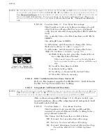
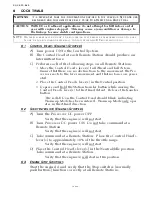
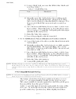
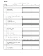
D) Using a Shaft Tach, measure the RPM of the Shaft and
record on Table 7-1:.
E) Manually move the Troll selector lever while periodi-
cally measuring the Shaft RPM. The typical Trolling
Valve can be adjusted so that the Shaft is rotating a 30 to
50 percent of the RPM’s measured and recorded on
Table 7-1:
F) Once the desired RPM has been reached, scroll to Func-
tion Code
L2
. Adjust the Value as described in Section
5-6.4.2.2, page 5-33, until the Troll push-pull cable aligns
with the Troll selector lever.
G) Enter the Value into memory.
H) Leave the push-pull cable disconnected.
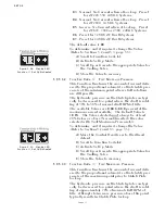
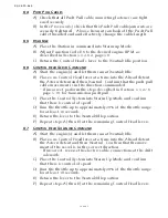
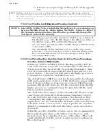
7-15.1.3 Troll Maximum Pressure Adjustments (Function Code L3)
A) Leave the Control Head lever in the Ahead detent with
Troll enabled.
B) Manually position the Troll selector lever while monitor-
ing the Shaft RPM. The typical trolling valve can be
adjusted to 70 to 80 percent of the RPM’s measured and
recorded on Table 7-1:.
C) Once the desired RPM has been reached, scroll to Func-
tion Code
L3
. Adjust the Value as described in Section
5-6.4.2.3, page 5-34, until the Troll push-pull cable aligns
with the Troll selector lever.
D) Enter the Value into memory.
E) Connect the push-pull cable.
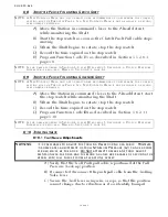
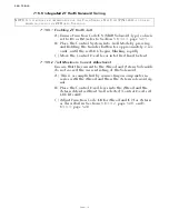
7-15.2 Integrated Solenoid Trolling
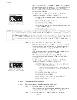
The Values selected for Function Code
L1
in Section 5-6.4.4.1,
page 5-37, are approximations for the various types of Gears.
The actual amount of current required for satisfactory troll opera-
tion may differ from the preset Values.
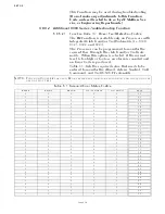
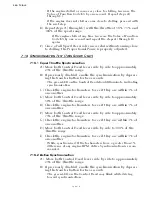
Table 7-2: provides typical current requirements for some of the
ZF Gears. As stated previously, the actual current required to
provide satisfactory operation may differ slightly from those
Table 7-1: Shaft RPM at Idle
Port
Starboard
NOTE: O
N
T
WIN
S
CREW
APPLICATIONS
,
THE
T
ROLL
M
INIMUM
AND
M
AXIMUM
P
RESSURE
ADJUST
-
MENTS
MUST
BE
DONE
ONE
SIDE
AT
A
TIME
INITIALLY
. O
NCE
EACH
T
ROLLING
V
ALVE
HAS
BEEN
ADJUSTED
INDIVIDUALLY
,
THEY
MUST
BE
OPERATED
AS
A
PAIR
AND
ADJUSTED
FURTHER
,
AS
NEC
-
ESSARY
.
NOTE: I
T
IS
STRONGLY
RECOMMENDED
THAT
THE
F
IELD
S
ERVICE
T
EST
U
NIT
(P/N 1400)
IS
UTILIZED
WHEN
ADJUSTING
THE
P
ROPORTIONAL
S
OLENOID
.
Содержание ClearCommand 9000 Series
Страница 1: ...ClearCommand 9000 Series Installation Operation and Troubleshooting Manual MM9000 I Rev C 2 5 08...
Страница 132: ......
Страница 133: ...APPENDIX A...
Страница 134: ......
Страница 139: ......
Страница 140: ...Page A 4...
Страница 143: ......
Страница 144: ...10...
Страница 148: ...Page A 18...
Страница 149: ...Page A 19 TEMPLATE...
Страница 150: ...Page A 20...
Страница 152: ...Page A 22...
Страница 154: ...Page A 24...
Страница 156: ...Page A 26...
Страница 157: ...Page A 27 Drawing 11488D 1 Twin Screw Single APS Connection Alternate Remote Switch...
Страница 158: ...Page A 28...
Страница 159: ...Page A 29 Drawing 11488D 2 Twin Screw Dual APS Connections...
Страница 160: ...Page A 30...
Страница 161: ...Page A 31 Drawing 11488D 3 APS Notes Page...
Страница 162: ...Page A 32...
Страница 164: ...Page A 34...
Страница 166: ...Page A 36...
Страница 170: ...Page A 40...
Страница 172: ...Page A 42...
Страница 176: ...Page A 46...
Страница 178: ...Page C 48 ZF Mathers LLC 12125 Harbour Reach Drive Suite B Mukilteo WA 98275...
Страница 179: ...APPENDIX B...
Страница 180: ......
Страница 234: ...Appendix B 6...
Страница 238: ...Appendix B 10...
Страница 242: ...Appendix B 14...
Страница 247: ...Service Field Test Unit Reference Manual MM13927 Rev E 4 07...
Страница 248: ......
Страница 250: ...Page ii Table of Contents...
Страница 264: ...SERVICE FIELD TEST UNIT MM13927 RvD 10 03 Page 3 2...
Страница 265: ...APPENDIX C...
Страница 266: ......
Страница 267: ...Appendix C 1 Drawing 12284A 1 ClearCommand Diagram all options...
Страница 268: ...Appendix C 2...
Страница 269: ...Appendix C 3 Drawing 12284A 2 ClearCommand Circuit Board Connections...
Страница 270: ...Appendix C 4...
Страница 271: ...Appendix C 5 Drawing 12284A 3 ClearCommand Drawing Notes Page...
Страница 272: ...Appendix C 6...

