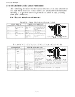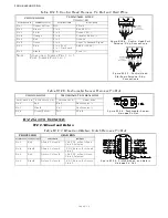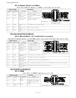
TROUBLESHOOTING
Page B11-2
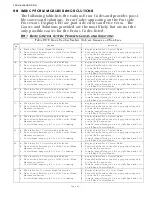
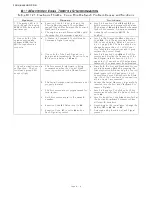
B11-1.3Servo Clutch Troubleshooting
B11-2A
CTIVE
S
YNCHRONIZATION
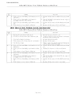
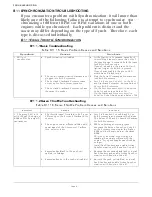
B11-2.1Basic Troubleshooting
Symptom
Causes
Solutions
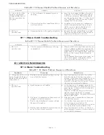
2. One or both of the
engines continually
changes RPM (hunts).
Will not synchronize
properly
a. A Control Head’s Command Signal is
varying.
a. Scroll to the Diagnostic Menu Function
Code H0. Go to the appropriate Station
A/D Count’s display. The Value should
not change by more than +/- 1 A/D Count.
If so, check the connections and if good,
replace the Control Head.
b. The push-pull cable’s travel from Idle to
Full is too short.
b. Lengthen the Governor or Carburetor’s
selector lever and attach the push-pull
cable to a point where the travel is in
excess of 2.00 inches (50,8mm).
3. Will not
synchronize.
a. Excessive bends in the push-pull cable(s). a. Reroute the push-pull cable(s) or install
Tach Sender and enable Active Synchro-
nization with Function Code E7.
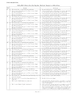
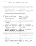
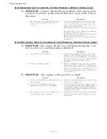
Table B11-17: Servo Clutch Problem Causes and Solutions
Symptom
Causes
Solutions
1. Will not
synchronize.
a. The Processor(s) think Astern is being
commanded.
a. Place both the Port and Starboard Proces-
sors into Warm-up Mode by pressing the
transfer button while moving the Control
Head levers to the Ahead detent. Both red
LED’s on the Control Head should be
blinking.
If not, reverse the wires at pins 5 and 7 at
the Control Head. Change the Clutch
direction with Function Code C5.
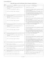
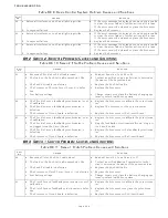
Table B11-18: Basic Problem Causes and Solutions
System
Causes
Solutions
1. The green LED is lit
solid, though the Engine
RPM’s differ by a signif-
icant amount.
a. The Tach Sender signal has been lost by
one or both Processors.
a. Scroll to Function Code H0. Go to the
Value for the Tach Sender’s input fre-
quency. If the frequency displayed is 0000,
the signal has been lost and the system
diverted to Equal Throttle Synch. Correct
the wiring or replace the Sender.
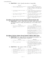
2. Will not
synchronize.
a. Synchronization is Disabled
a. At the Station-in-Command, move both
Control Head levers to more than 5% of the
speed range. Press and hold the transfer
button for 5 seconds.
If synch is disabled, the green LED will
light as long as the button is pressed.
If synch was enabled, the green LED would
have blinked twice.
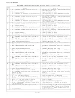
b. The Serial Communication Harness is not
plugged into both Processors.
b. Plug the Serial Communication Harness
into both Processors.
c. The Port and Starboard Processors have
the same ID number.
c. On the Port Processor, scroll to Function
Code A0 and enter a Value of 01.
On the Starboard Processor, scroll to Func-
tion Code A0 and enter a Value of 02.
D. The Port and Starboard Processors are not
set up for twin screw operation.
d. Scroll to Function Code A1, on the Port
and Starboard Processor. Enter a Value of
02 into both Processors.
Table B11-16: Servo Throttle Problem Causes and Solutions
Содержание ClearCommand 9000 Series
Страница 1: ...ClearCommand 9000 Series Installation Operation and Troubleshooting Manual MM9000 I Rev C 2 5 08...
Страница 132: ......
Страница 133: ...APPENDIX A...
Страница 134: ......
Страница 139: ......
Страница 140: ...Page A 4...
Страница 143: ......
Страница 144: ...10...
Страница 148: ...Page A 18...
Страница 149: ...Page A 19 TEMPLATE...
Страница 150: ...Page A 20...
Страница 152: ...Page A 22...
Страница 154: ...Page A 24...
Страница 156: ...Page A 26...
Страница 157: ...Page A 27 Drawing 11488D 1 Twin Screw Single APS Connection Alternate Remote Switch...
Страница 158: ...Page A 28...
Страница 159: ...Page A 29 Drawing 11488D 2 Twin Screw Dual APS Connections...
Страница 160: ...Page A 30...
Страница 161: ...Page A 31 Drawing 11488D 3 APS Notes Page...
Страница 162: ...Page A 32...
Страница 164: ...Page A 34...
Страница 166: ...Page A 36...
Страница 170: ...Page A 40...
Страница 172: ...Page A 42...
Страница 176: ...Page A 46...
Страница 178: ...Page C 48 ZF Mathers LLC 12125 Harbour Reach Drive Suite B Mukilteo WA 98275...
Страница 179: ...APPENDIX B...
Страница 180: ......
Страница 234: ...Appendix B 6...
Страница 238: ...Appendix B 10...
Страница 242: ...Appendix B 14...
Страница 247: ...Service Field Test Unit Reference Manual MM13927 Rev E 4 07...
Страница 248: ......
Страница 250: ...Page ii Table of Contents...
Страница 264: ...SERVICE FIELD TEST UNIT MM13927 RvD 10 03 Page 3 2...
Страница 265: ...APPENDIX C...
Страница 266: ......
Страница 267: ...Appendix C 1 Drawing 12284A 1 ClearCommand Diagram all options...
Страница 268: ...Appendix C 2...
Страница 269: ...Appendix C 3 Drawing 12284A 2 ClearCommand Circuit Board Connections...
Страница 270: ...Appendix C 4...
Страница 271: ...Appendix C 5 Drawing 12284A 3 ClearCommand Drawing Notes Page...
Страница 272: ...Appendix C 6...


