


Page A-44
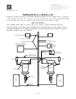
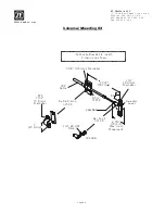
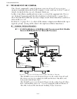
I) Cable Installation [Refer To Figure 2:]
1. Remove and retain the jam nut from the end of the 43C cable to be installed
in the Actuator/Processor.
2. Remove and discard the rubber boot and the rubber dust cover from the end
of the 43C cable to be installed in the Actuator/Processor.
3. Insert the end of the cable through the hole in the Actuator/Processor.
4. Thread the jam nut onto the end of the cable inside the Actuator/Processor.
5. On the outside of the Actuator/Processor, press the 43C Cable Retainer over
the notch in the 43C cable. This is intended to be a snug fit and may require
some force.
6. Install two screws through the 43C Cable Retainer and into the Actuator/Pro-
cessor.
7. Tighten the two screws securely with a Phillips Screwdriver.
8. Insert the 43C Cable Connect Nut through the cross-bar.
9. Thread the 43C Cable Connect Nut onto the end of the 43C cable.
10.After the cable connect nut is threaded onto the cable, tighten the jam nut
against the cross-bar using a 7/16 nut driver or socket and 7/16 open end
wrench.
11.Replace cover to Actuator/Processor. Refer to technical manual supplied
with the Actuator/Processor for any other required set up or adjustment.
NOTE: 43C
CABLE
AND
JAM
NUT
ARE
SUPPLIED
BY
OTHERS
.
Figure 2: Actuator/Processor Cable Installation
43C Cable
Connect Nut
Cross-bar
Lead Screw
Jam Nut
43C Cable
Retainer
43C Cable
Remove rubber boot
and dust cover
10917A
Содержание ClearCommand 9000 Series
Страница 1: ...ClearCommand 9000 Series Installation Operation and Troubleshooting Manual MM9000 I Rev C 2 5 08...
Страница 132: ......
Страница 133: ...APPENDIX A...
Страница 134: ......
Страница 139: ......
Страница 140: ...Page A 4...
Страница 143: ......
Страница 144: ...10...
Страница 148: ...Page A 18...
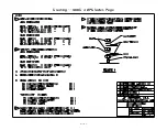
Страница 149: ...Page A 19 TEMPLATE...
Страница 150: ...Page A 20...
Страница 152: ...Page A 22...
Страница 154: ...Page A 24...
Страница 156: ...Page A 26...
Страница 157: ...Page A 27 Drawing 11488D 1 Twin Screw Single APS Connection Alternate Remote Switch...
Страница 158: ...Page A 28...
Страница 159: ...Page A 29 Drawing 11488D 2 Twin Screw Dual APS Connections...
Страница 160: ...Page A 30...
Страница 161: ...Page A 31 Drawing 11488D 3 APS Notes Page...
Страница 162: ...Page A 32...
Страница 164: ...Page A 34...
Страница 166: ...Page A 36...
Страница 170: ...Page A 40...
Страница 172: ...Page A 42...
Страница 176: ...Page A 46...
Страница 178: ...Page C 48 ZF Mathers LLC 12125 Harbour Reach Drive Suite B Mukilteo WA 98275...
Страница 179: ...APPENDIX B...
Страница 180: ......
Страница 234: ...Appendix B 6...
Страница 238: ...Appendix B 10...
Страница 242: ...Appendix B 14...
Страница 247: ...Service Field Test Unit Reference Manual MM13927 Rev E 4 07...
Страница 248: ......
Страница 250: ...Page ii Table of Contents...
Страница 264: ...SERVICE FIELD TEST UNIT MM13927 RvD 10 03 Page 3 2...
Страница 265: ...APPENDIX C...
Страница 266: ......
Страница 267: ...Appendix C 1 Drawing 12284A 1 ClearCommand Diagram all options...
Страница 268: ...Appendix C 2...
Страница 269: ...Appendix C 3 Drawing 12284A 2 ClearCommand Circuit Board Connections...
Страница 270: ...Appendix C 4...
Страница 271: ...Appendix C 5 Drawing 12284A 3 ClearCommand Drawing Notes Page...
Страница 272: ...Appendix C 6...