SET UP
Page5-20
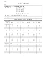
5-6.4.2 Clutch Solenoid Functions
This section along with Section 5-6.3.1 Clutch Basic Func-
tions allows the adjustment of Clutch Solenoid related
items:
5-6.4.2.1 Function Code C5 – Shift Solenoid Type
This Function Code must be left at the default value
unless a ZF-Hurth Gear is installed with proportional
Ahead and Astern Solenoids. When values
01
or
02
are selected, the current is limited to the solenoids.
The available Values are:
00
- All Shift Solenoids except ZF-Hurth (DEFAULT)
01
- ZF-Hurth Proportional Solenoids with 12V
Power
02
- ZF-Hurth Proportional Solenoids with 24V
Power
The default value of
00
is used with most types of
solenoids, with the exception of the ZF-Hurth Gears
with proportional Ahead and Astern solenoids.
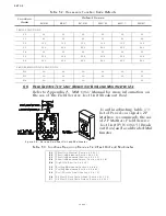
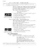
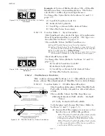
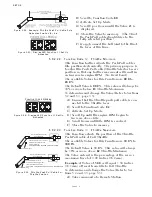
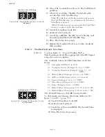
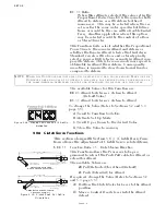
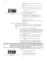
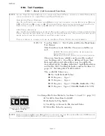
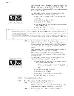
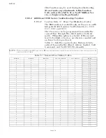
Figure 5-40: Display LED Function C7 Set Up
Activated
A) Move the Control Head lever to the Astern
detent.
B) Move the Clutch Selector Lever to the Astern
stop.
C) Does the cable’s ball joint and lever align?
• If yes, no further adjustment of this Function is
required.
• If no, continue with the next step.
D) Scroll to Function Code
C7
.
E) Activate Set Up Mode.
F) Scroll Up or Down until the ball joint and
Clutch Selector lever aligns perfectly.
G) Connect the ball joint to the Clutch Selector
lever.
H) Store the Value to memory.
I) Return the Control Head lever to the Neutral/
Idle position.
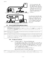
CAUTION: The maximum amount of current to these solenoids MUST be limited by
the control system. Failure to do so can cause permanent damage to the
solenoids. Depending on the voltage applied to the solenoids, adjust the
Value to 01 for 12V power and 02 for 24V power.
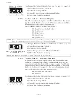
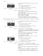
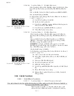
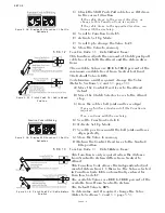
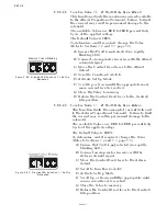
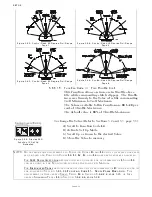
Figure 5-41: Display LED Function C5 Set Up
Activated
To change the Value (Refer to Sections 5-2 and 5-3,
page 5-5):
A) Scroll to Function Code
C5
.
B) Activate Set Up Mode.
C) Scroll Up to change the Value.
D) Store the Value to memory.
Содержание ClearCommand 9000 Series
Страница 1: ...ClearCommand 9000 Series Installation Operation and Troubleshooting Manual MM9000 I Rev C 2 5 08...
Страница 132: ......
Страница 133: ...APPENDIX A...
Страница 134: ......
Страница 139: ......
Страница 140: ...Page A 4...
Страница 143: ......
Страница 144: ...10...
Страница 148: ...Page A 18...
Страница 149: ...Page A 19 TEMPLATE...
Страница 150: ...Page A 20...
Страница 152: ...Page A 22...
Страница 154: ...Page A 24...
Страница 156: ...Page A 26...
Страница 157: ...Page A 27 Drawing 11488D 1 Twin Screw Single APS Connection Alternate Remote Switch...
Страница 158: ...Page A 28...
Страница 159: ...Page A 29 Drawing 11488D 2 Twin Screw Dual APS Connections...
Страница 160: ...Page A 30...
Страница 161: ...Page A 31 Drawing 11488D 3 APS Notes Page...
Страница 162: ...Page A 32...
Страница 164: ...Page A 34...
Страница 166: ...Page A 36...
Страница 170: ...Page A 40...
Страница 172: ...Page A 42...
Страница 176: ...Page A 46...
Страница 178: ...Page C 48 ZF Mathers LLC 12125 Harbour Reach Drive Suite B Mukilteo WA 98275...
Страница 179: ...APPENDIX B...
Страница 180: ......
Страница 234: ...Appendix B 6...
Страница 238: ...Appendix B 10...
Страница 242: ...Appendix B 14...
Страница 247: ...Service Field Test Unit Reference Manual MM13927 Rev E 4 07...
Страница 248: ......
Страница 250: ...Page ii Table of Contents...
Страница 264: ...SERVICE FIELD TEST UNIT MM13927 RvD 10 03 Page 3 2...
Страница 265: ...APPENDIX C...
Страница 266: ......
Страница 267: ...Appendix C 1 Drawing 12284A 1 ClearCommand Diagram all options...
Страница 268: ...Appendix C 2...
Страница 269: ...Appendix C 3 Drawing 12284A 2 ClearCommand Circuit Board Connections...
Страница 270: ...Appendix C 4...
Страница 271: ...Appendix C 5 Drawing 12284A 3 ClearCommand Drawing Notes Page...
Страница 272: ...Appendix C 6...

