


OPERATION
Page 2-14
2-13 A
UDIBLE
T
ONES
2-13.1 Basic Processor Tones
The Processor can produce numerous tones which inform the
operator of the status of the system or if any faults were to occur.
These tones are emitted from all Remote Stations regardless of
whether they are in command or not.
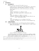
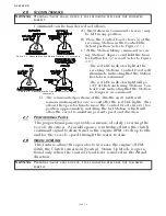
2-13.1.1 Slow Repetitive Tone
Detail information on this tone is in Appendix B
.
This tone is normal when DC power is first applied to the
System. This tone indicates that system initialization has
occurred, no Remote Station has command, the operator
can accept command at any Remote Station.
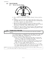
2-13.1.2 One Long, Three Short Tones
Detail information on this tone is in Appendix B.
This tone indicates that the command signal from a Control
Head’s potentiometer has gone out of range.
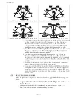
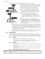
2-13.1.3 Steady Tone
Detail information on this tone is in Appendix B.
This tone indicates that the software program within the
Processor has quit running, due to low voltage or compo-
nent failure.
2-13.1.4 Five (5) Second Steady Tone
Detail information on this tone is in Appendix B.
This tone indicates that there has been a loss of Serial Com-
munication.
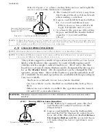
2-13.1.5 Three (3) Second Steady Tone
Detail information on this tone is in Appendix B.
This tone is heard if there is a stuck transfer button, or
when entering Back-up Mode, or if a Troll Solenoid error
occurs. (Back-up Mode and Troll Solenoid is not available
for all Processors.)
Figure 2-14: Slow Repetitive Tone
Figure 2-15: One Long, Three Short Tones
Figure 2-16: Steady Tone
Figure 2-17: Five (5) Second Steady Tone
Figure 2-18: Three (3) Second Steady Tone
Содержание ClearCommand 9000 Series
Страница 1: ...ClearCommand 9000 Series Installation Operation and Troubleshooting Manual MM9000 I Rev C 2 5 08...
Страница 132: ......
Страница 133: ...APPENDIX A...
Страница 134: ......
Страница 139: ......
Страница 140: ...Page A 4...
Страница 143: ......
Страница 144: ...10...
Страница 148: ...Page A 18...
Страница 149: ...Page A 19 TEMPLATE...
Страница 150: ...Page A 20...
Страница 152: ...Page A 22...
Страница 154: ...Page A 24...
Страница 156: ...Page A 26...
Страница 157: ...Page A 27 Drawing 11488D 1 Twin Screw Single APS Connection Alternate Remote Switch...
Страница 158: ...Page A 28...
Страница 159: ...Page A 29 Drawing 11488D 2 Twin Screw Dual APS Connections...
Страница 160: ...Page A 30...
Страница 161: ...Page A 31 Drawing 11488D 3 APS Notes Page...
Страница 162: ...Page A 32...
Страница 164: ...Page A 34...
Страница 166: ...Page A 36...
Страница 170: ...Page A 40...
Страница 172: ...Page A 42...
Страница 176: ...Page A 46...
Страница 178: ...Page C 48 ZF Mathers LLC 12125 Harbour Reach Drive Suite B Mukilteo WA 98275...
Страница 179: ...APPENDIX B...
Страница 180: ......
Страница 234: ...Appendix B 6...
Страница 238: ...Appendix B 10...
Страница 242: ...Appendix B 14...
Страница 247: ...Service Field Test Unit Reference Manual MM13927 Rev E 4 07...
Страница 248: ......
Страница 250: ...Page ii Table of Contents...
Страница 264: ...SERVICE FIELD TEST UNIT MM13927 RvD 10 03 Page 3 2...
Страница 265: ...APPENDIX C...
Страница 266: ......
Страница 267: ...Appendix C 1 Drawing 12284A 1 ClearCommand Diagram all options...
Страница 268: ...Appendix C 2...
Страница 269: ...Appendix C 3 Drawing 12284A 2 ClearCommand Circuit Board Connections...
Страница 270: ...Appendix C 4...
Страница 271: ...Appendix C 5 Drawing 12284A 3 ClearCommand Drawing Notes Page...
Страница 272: ...Appendix C 6...