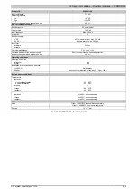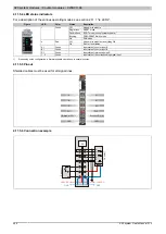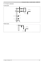
X20 system modules • Counter modules • X20DC1198
X20 system User's Manual 3.10
699
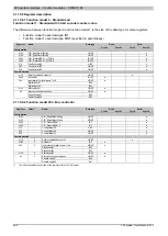
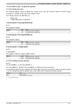
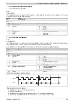
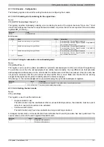
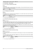
4.11.6.9.3 SSI encoder configuration register
4.11.6.9.3.1 Standard configuration
Name:
ConfigOutput14
This configuration register is used to set the coding, the clock rate and the number of bits. Default = 0. This must
be set once using an acyclic write command.
Data type
Value
UINT
See bit structure.
Bit structure:
Bit
Name
Value
Information
0 - 5
SSI value valid bits
x
00
1 MHz
01
500 kHz
10
250 kHz
6 - 7
Clock rate
11
125 kHz
8 - 13
SSI number of bits
x
Number of bits including leading zeros
14
Reserved
0
0
Binary coding
15
Keying
1
Gray coding
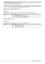
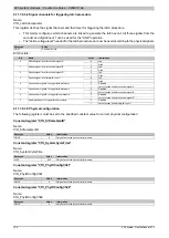
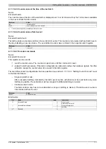
4.11.6.9.3.2 Extended configuration
Name:
ConfigAdvanced
This configuration register is used to set the coding, the clock rate, the number of bits and the monostable multivi-
brator settings. Default = 0. This must be set once using an acyclic write command.
It only differs from ConfigOutput14 by data length and additional monostable multivibrator testing.
Data type
Value
UDINT
See bit structure.
Bit structure:
Bit
Name
Value
Information
0 - 5
SSI value valid bits
x
00
1 MHz
01
500 kHz
10
250 kHz
6 - 7
Clock rate
11
125 kHz
8 - 13
SSI number of bits
x
Number of bits including leading zeros
14
Reserved
0
0
Binary coding
15
Keying
1
Gray coding
00
Check OFF, no additional clock bit
01
Check set to High level
10
Check set to Low level
16 - 17
Monostable multivibrator testing
11
Level is clocked but ignored
18 - 31
Reserved
0
Reserved
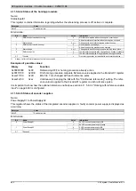
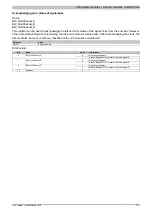
Transfer to synchronous serial interface
Clock
Data
Bit n
Bit n - 1
Bit n - 3
Bit 1
Bit 0
1
2
3
4
Measurement value processing
1 Starting bit ... Stores the measurement value
2 Output of first data bit
3 All data bits are transferred, monostable multivibrator time starts counting down.
4 Monostable multivibrator returns to its initial state. A new transfer can be started.

