X20 system modules • Expandable bus controllers • X20BC1083
1710
X20 system User's Manual 3.10
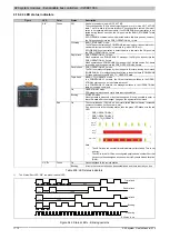
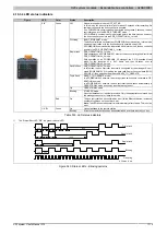
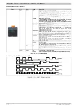
4.19.2.4 LED status indicators
Figure
LED
Color
Status
Description
Off
No power supply or mode is NOT_ACTIVE.
The controlled node (CN) is either not getting power, or it is in the NOT_ACTIVE
state. The CN waits in this state for about 5 seconds after a restart. Communi-
cation is not possible with the module. If no POWERLINK communication is de-
tected during these 5 seconds, the CN goes into the BASIC_ETHERNET state
(flickering).
If POWERLINK communication is detected before this time passes, however,
the CN goes directly into the PRE_OPERATIONAL_1 state.
Flickering
BASIC_ETHERNET mode.
The CN has not detected any POWERLINK communication. It is possible to com-
municate directly with the CN in this state (e.g. with UDP, IP, etc.).
If POWERLINK communication is detected while in this state, the CN goes into
the PRE_OPERATIONAL_1 state.
Single flash
PRE_OPERATIONAL_1 mode.
When operated on a POWERLINK V1 manager, the CN goes directly into the
PRE_OPERATIONAL_2 state.
When operated on a POWERLINK V2 manager, the CN waits until an SoC frame
is received and then goes into the PRE_OPERATIONAL_2 state.
Double flash
PRE_OPERATIONAL_2 mode.
The CN is normally configured by the manager in this state. Issuing a command
(POWERLINK V2) or setting the data valid flag in the output data (POWERLINK
V1) then switches to the READY_TO_OPERATE state.
Triple flash
READY_TO_OPERATE mode.
In a POWERLINK V1 network, the CN automatically switches to the OPER-
ATIONAL state as soon as input data is present.
In a POWERLINK V2 network, the manager switches to the OPERATIONAL
state by issuing a command.
On
OPERATIONAL mode.
PDO mapping is active and cyclic data is being evaluated.
Green
Blinking
STOPPED mode.
No output data is produced or input data supplied. It is only possible to enter or
leave this state after the manager has given the appropriate command.
S/E
1)
Red
On
The controlled node (CN) is in an error state (failed Ethernet frames, increased
number of collisions on the network, etc.).
If an error occurs in the following states, then the green LED blinks over the red
LED:
•
PRE_OPERATIONAL_1
•
PRE_OPERATIONAL_2
•
READY_TO_OPERATE
t
t
t
"S/E" LED
Status
Green
Error
Red
Note:
•
The LED blinks red several times immediately after startup. This is not
an error.
•
The LED is lit red for CNs with configured physical node number 0 but that
have not yet been assigned a node number via Dynamic Node Allocation
(DNA).
On
Link established to the remote station
L/A IFx
Green
Blinking
A link to the remote station has been established and there is activity on bus.
Table 498: LED status indicators
1)
The Status/Error LED "S/E" is a green/red dual LED.
200
200
1000
200
200
200
200
1000
200
200
All times in ms
Flickering
Blinking
Single flash
Triple flash
200
200
200
1000
Double flash
Figure 544: Status LEDs - Blinking patterns


